Project: HiCAD Feature Technology
Step 1: Create Construction
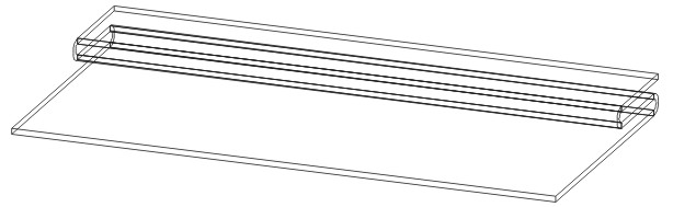
Example of a sheet part
Step 2: Create Design Variant base part
Now mark the dummy part as design variant base body.
The dummy part is only used as the basis for the design variant in the drawing in which the variant is generated. It is used there, for example, to include the variant's parameter variables. It does not feature in the drawing in which the variant is fitted.
Step 3: Create the part's variables
The design variant base body's variables become the design variant's parameters. In other words, the system prompts for these variables when the variant is fitted. If the variables have a comment, it is displayed instead of the variable name during the prompt.
The variables need to be set in the dummy part for the design variant.
The system then prompts for an edge.
Now assign the variables to the elements.
Step 4: Marking the Part as the starting point for processing within the Design Variant
On the one hand, design variants can process one or more parts of the drawing in which they are used and, on the other hand, also introduce new parts into the drawing. The formula entered for the generation feature of the part indicates how to proceed with which sub-part of the design variant base body:
Formula for the Processed Part: All features apart from the generation feature (in this case, the base sheet) are attached to the log of the part in the fitting drawing. The formula determines which part in the fitting drawing. (In this example, the user will doubtless only want to choose the edge to which the addition is to be made. The part therefore results from the formula part_of_edge(connecting edge)
Formula for Assembly: During fitting, the part becomes a sub-part of the part specified in the formula.
Step 5: Create Design Variant
The extension for the design variant is FMV (Feature Modifying Variant). As, internally, it is a part that is saved, as was the case with the previous feature variants, the files <name>.FMV.KRP, <name>.FMV.KRP.FEA etc. also exist, in addition to <name>.FMV.
Step 6: Insert Design Variant
The system prompts for the variables in turn (alphabetically). This example requires you first to identify a connecting edge. The design variant is then inserted.
A feature step is produced in the log: Design variant. Special sub-points for the design variant are:
Opens a variable table containing the variant's parameter variables.
If you expand the entry, you will see the log for the design variant. In particular, the log may contain errors which have occurred during fitting.


|
© Copyright 1994-2019, ISD Software und Systeme GmbH |