Project: HiCAD Dach/Wand/Fassade
Example: Create Parts with Connection Parameters - Step 3
Step 3: Insert and link element installation and sub-structure
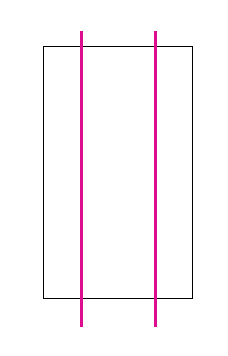
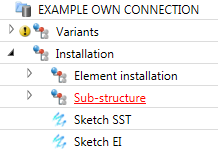
- Create two sketches - one for the element installation and one for the sub-structure. The element installation consists of a simple rectangle, the sub-structure of two straight lines. The exact dimensions are not important here; however, the sketch for the sub-structure should be placed 10 mm behind the sketch for the element installation.
- Choose Civil Engineering functions > Element installation > Element installation and place the previously created variant Asbestos cement panel on the sketch for the element installation. .
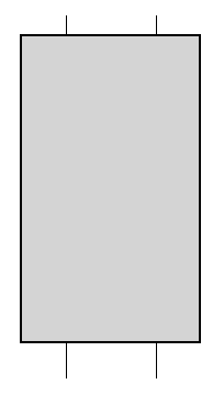
- Then, choose Civil Engineering functions > Element installation > Sub-structure and place the variant T-beam onto the other sketch.
- Create a new assembly called Installation and move the element installation and the sub-structure into this assembly.
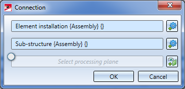
- Now, choose Civil Engineering functions > Element installation >Connection.
- Select the element installation as the first part and the sub-structure as the second part. The Processing plane function remains deactivated.
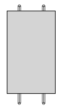
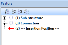
The two parts are now connected. In the Feature logs of the two parts there is now a new entry called Connection. The model drawing, however, remains unchanged. The reason for this is that the variants have not been prepared for the connections yet. If the variants had already been prepared at this point, you could insert the connection now.
In the next two steps the variants will be prepared in such a way that bores will be automatically created as a result of the connections.
Next step: Plan Bores in Asbestos Cement Panel


Connection Parameters
|
© Copyright 1994-2019, ISD Software und Systeme GmbH
Version 2402 - HiCAD Dach/Wand/Fassade
Date: 14/10/2019
|
> Feedback on this topic
|