> Parameters, Individual
Project: HiCAD Sheet Metal
Sheet Metal > Sheet development > Update > Parameters, Individual
Sheet Metal > Sheet development > Update > Parameters, Default setting 
Sheet Metal > Sheet development > Update > Parameters, All 
Use these functions to define the parameters of 2-D blanks as they could be created up to HiCAD 2016. From HiCAD 2017 onwards, only 3-D developments can be created.
Depending on the selected function, you can change:
You can - in one drawing - derive several blanks with different parameter settings from a Sheet Metal part. The parameter settings will be saved in the blank. In this way you can save blanks intended for DXF export for, e.g. LVD and Bystronic with their different parameters in one drawing.
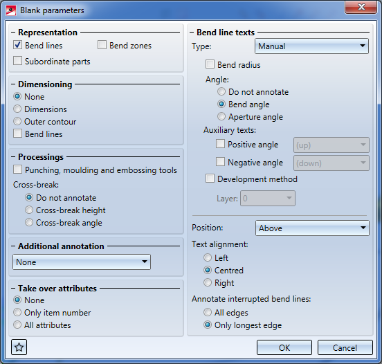
In the dialogue window, activate the checkboxes and radio buttons of the parameters that you want to be shown in the blank.
|
Representation |
A Bend line can also be indicated by means of two short lines, one at the beginning and one at the end of the bending edge (Bend zone) instead of one, continuous line. Length, distance to outer contour, line type and colour can be set in the Configuration Editor at Compatibility > Sheet development up to HiCAD 2016 > Extended settings > Bend line: ... . Positive and negative bend lines can be configured independently.
|
|
Dimensioning |
Use the Dimensions option to dimension only the largest extension in X- and Y-direction. Select Outer contour do dimension the complete contour. If you have activated the Bend lines option, the bend line running parallel to the outer contour will be dimensioned - irrespective of the other dimensioning settings.
|
|
Processings |
If you activate the Punching, moulding and embossing tools checkbox, the WZNR column of the catalogue will be output in the development. |
|
Additional annotation |
Use this option to create an additional text above or below the blank, which will be evaluated by the software of the sheet processing machine LVD or Bystronic). If you select the Text block, inside or ...outside option, the dimensions and the article number will be shown. The text is defined via the Development_Textblock.ftd file in the SYS directory, and generated from the part attributes. |
|
Take over attributes |
Designation 1 of the part attributes will be taken over if the option All attributes has been selected in the Take over attributes dialogue window. |
|
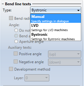
Bend line texts |
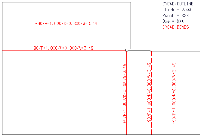
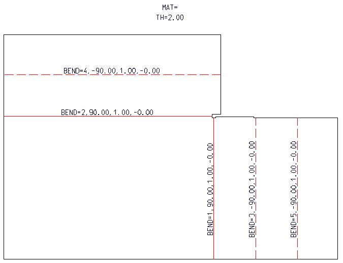
Here you can configure the text next to the bend line. You can either specify the settings in the dialogue manually, or select texts that had been adjusted for Bystronic or LVD.
If you want to enter the angles, you can choose between Bend angle and Aperture angle. For positive and negative angles, additional texts can be activated. To display the allowance method in the development, activate the Development method checkbox and select a Layer for the text. Layer 0 is active by default. |
|
Position |
In this area you can specify the position of the bend angle annotations. Beneath Text alignment you can specify the alignment of the texts created for the development. To show the bend angle on all segments of interrupted bend lines, activate All edges. |
|
|
The settings can be saved as favourites and re-used at any time. To do this, click the The blank settings for LVD, Bystronic and Lantek Expert machines have been predefined and are saved as favourites. More information on favourites management can be found in the Manage Favourites topic of the HiCAD Basics help. |
After confirming with OK, the specified parameters will be applied to new and existing blanks.
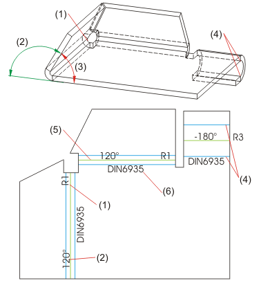
(1) Bend radius
(2) Bend angle 120°
(3) Aperture angle 60°
(4) Bend zone
(5) Bend line
(6) Allowance method


Overview of Functions (3-D SM) • General Information on Sheet Metal Processing • Development (3-D SM) • Allowance Method for Developments (3-D SM)
|
© Copyright 1994-2019, ISD Software und Systeme GmbH |