Project: HiCAD Sheet Metal
Civil Engineering functions > Sheet Metal > Mitre cut
The Mitre cut Design Variant enables you to mitre-cut sheets, bend zones and flanges in one step. The bend zone will either be trimmed or adapted in the process.
The flanges can be located in different planes and do not need to overlap. Proceed as follows:
(1) First front side
(2) Second front side
If the connection is possible after selection of the above elements, the following dialogue window will be displayed.
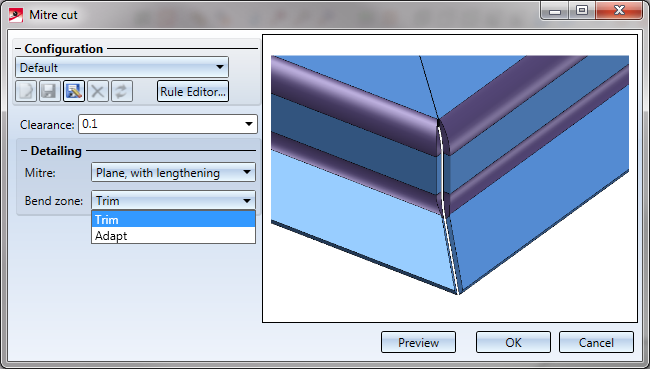
The input fields are initialised with default values and can be modified if desired.
The following combinations are possible:
|
|
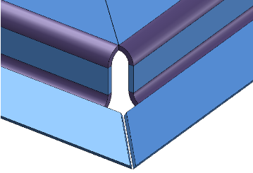
Mitre cut: Individual, with lengthening |
|
|
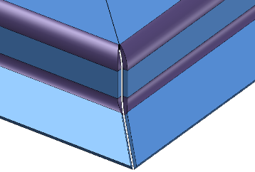
Mitre cut: Plane, with lengthening Bend zone: trimmed |
|
|
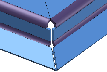
Mitre cut: Plane, with lengthening Bend zone: adapted |
If you select Preview, the mitre cut will be applied, but the dialogue window will remain open, enabling you to change parameters and check the result in the drawing if required. If you select OK, the mitre cut will be applied, and the dialogue window will be closed. If you select Cancel, the window will be closed, but no changes will be applied.
All attached flanges and bend zones will be lengthened and mitre-cut if required.
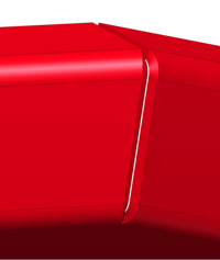
(3) Sheets, bend zones and flanges mitre-cut, plane with lengthening, bend zones trimmed
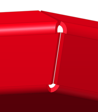
Plane with lengthening, bend zones adapted
 Please note:
At the top of the window you can save a configuration for later re-use, or load already existing ones.


Sheet Metal Design Variants (3-D SM)
|
© Copyright 1994-2019, ISD Software und Systeme GmbH |