 > Settings, permanent > CS display
 Project: HiCAD Basics
Drawing > Others > Extras > Settings, permanent > CS display
A sketch of the coordinate system is shown as an orientation aid in the drawing. The x-axis is displayed in red, the y-axis in green and the z-axis in blue. In 3-D coordinate systems, the index of the coordinates indicates the number of the view.

The size of the coordinate system can be changed by means of the
 CS display
function. Furthermore, you can use this function to specify in which views the coordinate system is to be displayed.
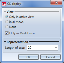
Specify via the radio buttons whether the coordinate system is to be displayed in all views or only in the active view. Specify whether this setting is to apply only to the Model area or to the Model and sheet area by activating or deactivating the Only in Model area checkbox . If the checkbox is activated, no coordinate systems will be displayed in the Sheet area (irrespective of the chosen radio button).
The Length of axes value determines the size of the coordinate system display. The value must be greater than 0.
 Please note:
 (Drawing > Others > Colour Editor). The colours for the axes can be chosen from the list on the Special colours tab.

The CS display function does not refer to this coordinate system that can be hidden and shown via F3, but to the coordinate system that is displayed by default in the origin (0,0,0) of each view.


|
© Copyright 1994-2019, ISD Software und Systeme GmbH |