 Double-sided offset with end caps
Project: HiCAD 3-D
Sketch > Derive > Offset > Double-sided offset with end caps
Use this function to insert double-sided offsets (i.e.parallel line elements to both sides of a selected graphical element) into the active sketch or 3-D sketch. You can also specify in the process how the corners and the ends of the resulting composite edges are to be handled.
When you call the function, the Double-sided offset with end caps dialogue window will be displayed.
Offset
Here you specify the distance of the parallels to their reference element.
Fillet corners
If you want the corners of the resulting composite edges to be filleted, activate this checkbox and enter a fillet radius.
Ends
In this area of the dialogue window you specify how the ends of the two resulting composite edges are to be handled. The following options are available:
| Line |

|
The composite edges are connected by a line. The corners between composite edge and line can also be filleted if desired. To do this, activate the Radius checkbox and enter the desired value. |
| Arc |

|
The composite edges are connected by an arc. The end point of the reference element is located on the arc. |
| Offset arc |

|
The composite edges are connected by an arc, with a specified distance (in the Offset input field) of the end point of the reference element to the arc. |
| Without end cap |

|
The composite edges are not connected. |
Delete selected lines
If you want the selected original lines to be deleted after generation of the parallels, activate this checkbox.
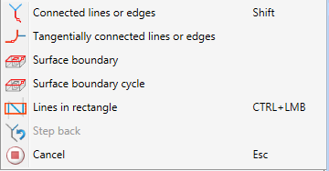
Specify the desired settings. Then, identify the desired edges. For this you can also use the functions of the context menu that you activate with a right-click during the edge identification process.
|
|
Connected lines or edges* Use this function to select all lines or edges that are connected to the next identified edge in one step. The lines and edges will be selected up to a point where a continuation would no longer be unambiguous. This does not apply to the edges of a solid.
|
|
|
Tangentially connected lines or edges* Choose this function if you also want to select all tangentially connected lines or edges when identifying the next line or edge. |

|
Surface boundary * Use this function to take over all edges forming the boundaries of a surface in one step. Select the desired facet with the cursor or by choosing two edges. These can also be edges of a solid or of a part with free surfaces. |
|
|
Surface boundary cycle* Use this function to select all edges forming the boundaries of a facet in one step. Select the desired facet with the cursor or select it by identifying two edges. These can also be edges of a solid or of a part with free surfaces. |
|
|
Lines in rectangle (CTRL+LMB)* Use this function to select lines by means of a selection rectangle. Please note that only lines of the active part will be considered. If the rectangle is drawn from the top left to the bottom right, all lines which are completely located within the rectangle will be selected. If the rectangle is drawn from the top right to the bottom left, lines only portions of which are located within the rectangle (i.e. intersect with the rectangle) will be selected as well. The selected lines will be highlighted in a different colour. You can also call the function via the keyboard. Proceed as follows:
|
|
|
Step back If you want to undo one or several steps of the process in order to make corrections, select this option (if required, several times). |
|
|
Cancel (Esc) Cancels the function. |
|
Important note on the selection functions: Normally, already selected lines and edges will be de-selected if you click them again. For the above functions marked with an asterisk *, however, the following applies: If you click lines that have already been selected or if already selected lines are located in a selection, they will not be removed from the selection! |
|
The selected edges will be highlighted and a preview of the offset will be shown.
Click OK to create the offset and end the function.
If you select Apply, the offset will also be created, but the function remains active, enabling you to create further offsets - also with other settings if desired. In the process, you can also select edges of previously created offsets.
If you middle-click in the drawing while the dialogue window is displayed, the following will happen:
(1) Original sketch, (2) Offset without filleted corners and end caps, (3) Offset with filleted corners without end caps, (4) Offset with filleted corners and end caps: Lines, (5) Offset with filleted corners and end caps: Offset - Arc (6) Offset with filleted corners: Arc
 Please note:
To be on the safe side, you should always apply the Sort GE function to unknown sketches.
The automatic assigning of HCM constraints can be switched on or off by selecting Sketch > HCM > Tools > Settings and activating / deactivating the corresponding checkbox.


Sketch Functions (3-D) • Sketch Technology (3-D) • Lines and Polylines (3-D)
|
© Copyright 1994-2019, ISD Software und Systeme GmbH |


