 > Spirals

Project: HiCAD 3-D
Sketch > Draw > Freehand > Spirals
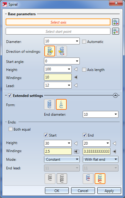
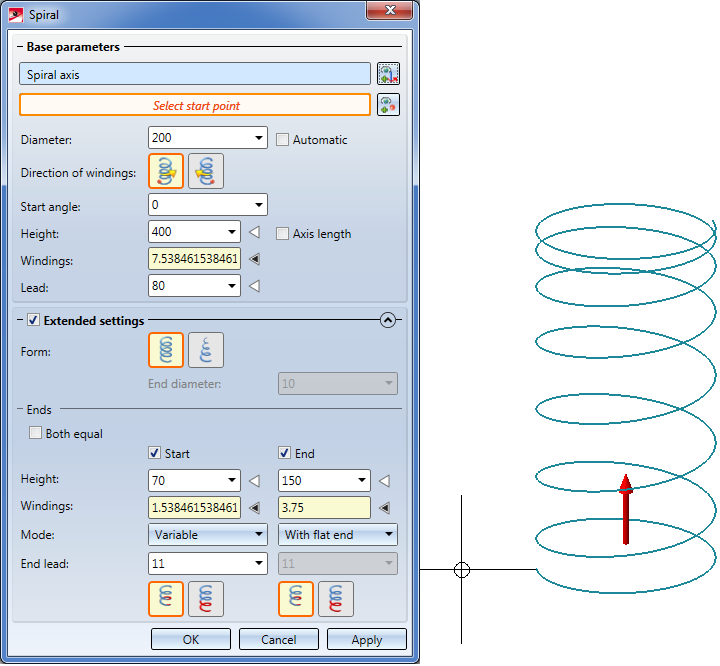
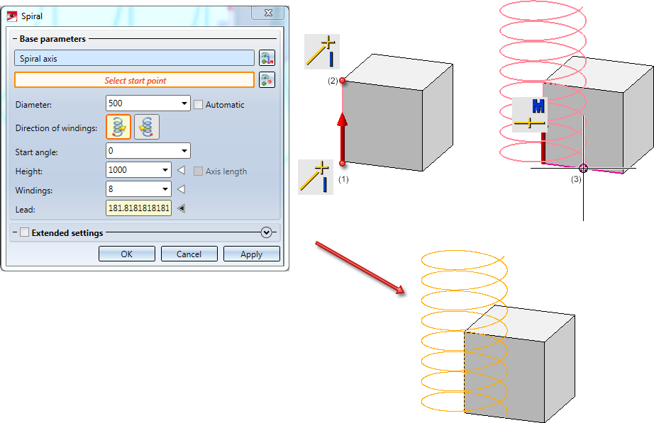
When you call the function, the following dialogue window will be displayed:
 Please note:
The creation of spiral-shaped curves as polygon lines or compound curves can be achieved by a subsequent applying of the Replace line function.
The Topics:

When the dialogue window appears, the Select axis input field will be active. Specify the centre axis about which the spiral is to rotate, either via
Right-click to open a context menu with further options for direction specification:
|
|
Origin The start point of the axis is placed into the origin of the active coordinate system. |
|
|
|
X-axis Chooses the X-axis of the active coordinate system as spiral axis. |
|
|
|
Y-axis Chooses the Y-axis of the active coordinate system as spiral axis. |
|
|
|
Z-axis Chooses the Z-axis of the active coordinate system as spiral axis. |
|
|
|
Step back Jumps one step back (if possible) |
|
|
|
Cancel Ends the function without creating the spiral |
|
To change the axis, click on the  symbol and select a new axis as described above. After selecting the spiral axis, the text Spiral axis will be shown in the dialogue window. In the drawing, the axis as well as a preview of the spiral based on the current parameters will be dynamically visualized.
After spiral axis selection, HiCAD will prompt you to specify the start point of the spiral. As soon as you choose the start point, it will be visualized in the drawing and the text Start point of spiral will be shown. To correct the start point, click the  symbol.
|
Diameter |
The diameter can either be determined automatically, or manually by means of a value input. Determined here is the diameter of a circle the centre point of which lies on the spiral axis. When you choose Automatic, the radius of this circle will be the distance of the start point from the spiral axis. The Diameter field will then not be evaluated. |
|
Direction of windings |
Windings of spirals can be running either in clockwise or anticlockwise direction. Click the desired symbol to specify the direction.
|
|
Start angle |
By specifying a start point, the spiral can be additionally rotated about this angle. |
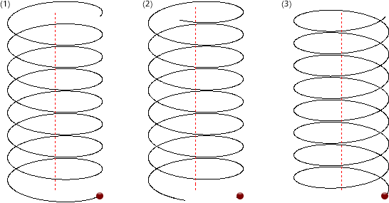
(1) anticlockwise; (2) anticlockwise, with start point; (3) anticlockwise. Red point = start point.
The route of the spiral is determined via 3 parameters, 2 of which can be freely defined, resulting in the automatic calculation of the third parameter. Which of the 3 parameters are to be automatically calculated can be determined by clicking on the arrow symbol  next to the relevant parameter. The black arrow symbol
  indicates that this parameter will be calculated from the values of the 2 other parameters - the input field of this parameter is therefore locked, value inputs are not possible here.
|
Height |
Total height of the spiral Instead of making a value input here you can also activate the Axis length checkbox. In this case, the length of the spiral axis will be used as height. The Height input field will then be locked.
|
|
Windings |
Number of windings |
|
Lead |
Height difference required by one winding |
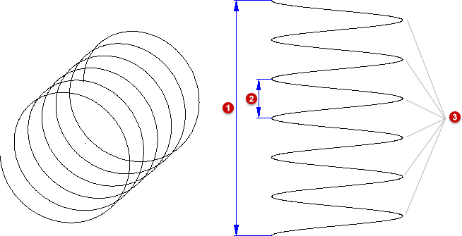
Example of a spiral: (1) Height, (2) Lead, (3) Number of windings
Please note:
When switching the calculation mode (e.g. from automatic Height calculation to automatic number of Windings calculation), the new value to be entered (e.g. Height) will be initialized on the basis of the value that was previously calculated there, so that the curve route will not change. However, if you use formulas for the parameters, you should select the Mode first, since a switching of the Mode can lead to a loss of the underlying formulas!
Click the  icon to open the Extended settings area with further parameters (Default. closed). For instance, you can choose between a cylindrical and a conical shape of the spiral here, or define different routes at the start and the end of the spiral.
|
Form |
Here you can choose between a
If you select the conical shape, the Diameter value entered in the Base parameters area will only describe the start diameter of the spiral, and the End diameter can be specified separately. |
|
Ends |
Here you can modify the route at its start and end by adjusting the lead accordingly. The modifications at the start and the end can differ if desired. |
|
|
Both equal
Height/Windings
Mode
Segment in helix/Projection (only for the modes "With flat end" and " Variable")
symbol to specify whether the modified end segment is to be created as an additional projection beyond the spiral that was defined described by means of the base parameters, or or whether exactly this spiral is to be preserved in its total size and needs to be modified accordingly. In the latter case the lead (from the Base parameters) will no longer describe a constant lead, but the average lead through the spiral. |
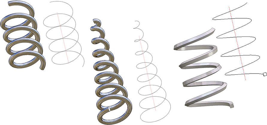
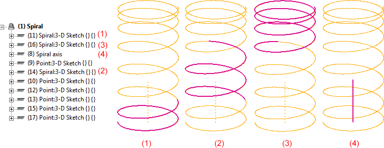
The following image shows a conical spiral with different modifications at the start and the end.
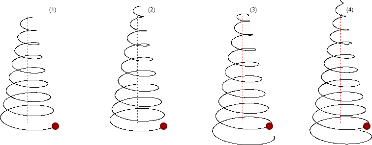
(1) Without settings for Start/End; (2) Start: Mode Variable, Segment in helix, End: Mode Variable, Projection; (3) Start: Mode Constant, End: Mode With flat end, Segment in helix; (4) Start and End Both equal, Mode Constant
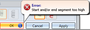
Click Apply to create the spiral as shown in the preview. If the creation is not possible to to incorrect or missing inputs, this will be indicated by the  symbol on the OK button. Correct your entries.
After clicking Apply the dialogue window will remain open, allowing you to create further spirals if desired. These will be assigned to the active 3-D Sketch.
When you click OK, the spiral will also be created, but the dialogue window will be closed. If you click Cancel, the window will be closed, and spirals that have not been created yet will be lost.
Spirals can also be used as guidelines for the C-edge sweep function. This is now even possible if further sketch elements have been attached to the start or end of the spiral. Please note however that in such cases these elements must have been linked to the start or end of the spiral via a Coincidence constraint!
Example 1
The image below shows spirals that have been used as guidelines for the placing of a circular cross-section (C-edge sweep function).
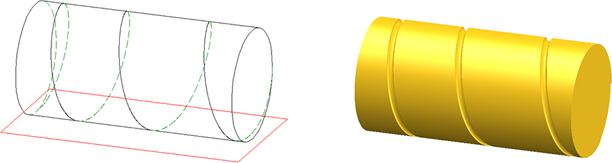
Example 2
Here a spiral has been "wrapped" around a cylinder, and has then been used as a guideline for the placing of a circular cross-section. After this, the resulting body has been subtracted from the cylinder.
Example 3:
In this example, further edges have been added both at the start and at the end of a spiral. The start point of the edges lies in the start (or end) point of the spiral, where Coincidence constraints have been assigned. Then, the C-edge sweep function was used to place a circular cross-section along this "expanded spiral".
Spirals are automatically parameterised upon their creation, i.e. a corresponding HCM model will be generated. Via this HCM model spirals can be changed subsequently. If the spiral is saved as a 3-D part (KRA), it will be saved together with the HCM model. This means that once created, spirals can be reused and individually adjusted in any model drawings.
In the ICN the 3-D sketch will be marked with the  symbol.
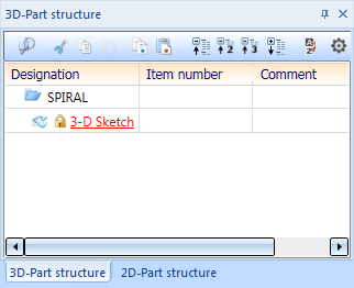
The associated HCM model will be displayed in the HCM window.
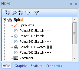
The following main entries belong to each spiral:
For spirals with different route at the start and/or end the HCM model will obtain two additional entries for the start and the end of the spiral:
If a HCM entry has been selected with the cursor, the corresponding element will be highlighted in the drawing (Special colour Marking 1).
Example:
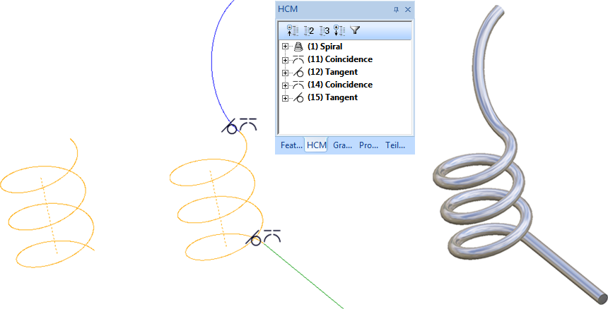
For the spiral shown below different routes have been selected for the start and the end.
If you take a look at the associated HCM model, the spiral virtually consists of 3 segments, namely, one start, one middle and one end segment. For each of these segments a HCM entry called Spiral:3-D Sketch exists.
Furhermore, the start points of the segments, the end point of the end segment, the start point and the end point of the spiral axis each have one HCM entry called Point: 3-D sketch. The spiral axis has an entry called Spiral axis. The start segment and the end segment each have one HCM entry called Point: 3-D sketch for the end of the start segment and one for the start of the end segment.
Associated HCM model (the sequence of entries may vary)
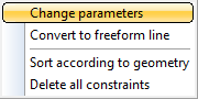
To modify a spiral subsequently you use the Change parameters function of the HCM context menu. To open the menu, right-click on the HCM entry Spiral.
When you call the Change parameters function the Spiral dialogue window will be displayed with the current parameters of the spiral. Change the data and confirm with OK.
All value inputs in the Spiral dialogue window can also process variables. If the values assigned to the variables are changed with the
 (Sketch > Tools) or the
  function,
 the HCM model and thus the spiral will be automatically adjusted via HCM recalculation.
Please note
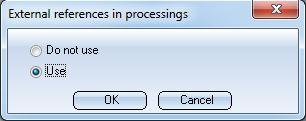
Parameterized spirals cannot be modified with the HiCAD processing functions. If a modification is attempted, the following message will be displayed:
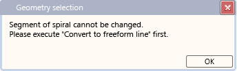
However, please note that the HCM model of the spiral will be lost after its conversion to a freeform line!
For spirals, too, the feature setting External references in processings will be assessed. Based on this setting the behaviour regarding external references will be adjusted.
Example:
The active drawing contains a cuboid. Now a spiral will be created which uses an edge or two points (e.g. start point, end point or centre of a cuboid edge) as an axis. For the start point of the spiral another point on the cuboid will be chosen. This means that the spiral axis as well as the start point refer to the cuboid, i.e. have external references.
(1) and (2) start and end points of the spiral axis, (3) start point
The feature setting External references in processings determines how the spiral behaves, if the spiral itself or the cuboid are being moved.
In order to activate this setting for the spiral, right-click into the spiral's (empty) feature log and select External references in processings...from the menu. Afterwards select the desired option. The ISD default setting is Do not use.
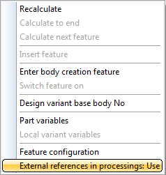
If you select the Use option and then move the cuboid, the references to the cuboid will be considered when changing the spiral with the Change parameter function in the HCM context menu or when updating the HCM model with the 3-D Standard > HCM > Tools  function.
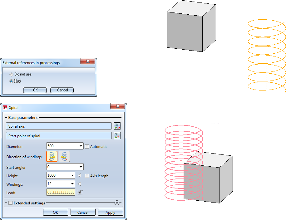
However, if the Do not use option is selected, the references to the cuboid will not be considered when changing/updating the spiral.
Another example would be a spiral aligned with a cylinder with the spiral axis in the centre of the base area, the end point in the centre of the top area and the start point in a quadrant point in the base area.

3-D Sketch (3-D) • Sketch Functions (3-D)
|
© Copyright 1994-2019, ISD Software und Systeme GmbH |


 Clockwise
 Anticlockwise (Default)
 Cylindrical shape of the spiral with a constant diameter (Default) and a
  Conical shape of the spiral.
  Segment in helix or the
  Projection