 > Powder marking lines
Project: HiCAD 3-D
3-D Standard > Standard Processings > Bore > Powder marking lines
Use this function to manually or automatically project so-called powder marking lines onto the outer surfaces of the active/selected part. Powder marking lines are caused by the outer surfaces of parts lying within the outer surface of the active/selected part (taking certain tolerance values into account). In this way you can, for example, highlight the contours of parts which are to be welded together.
First, select the part to which you want to apply the powder marking line. If desired, you can also apply the powder marking lines to part lists (multiple selection) in one step. If does not matter whether these part lists contain individual parts or assemblies.
When you call the function, the dialogue window below will be displayed:
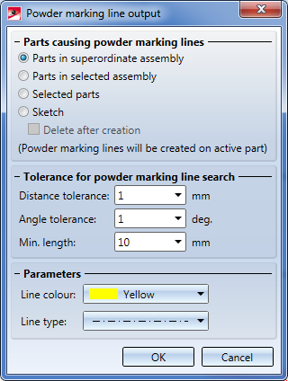
Tolerance for powder marking line search
In this area you can specify various tolerance values to determine which surfaces and edges are to be considered for powder marking line search:
Considers only surfaces whose distance to the (parallel) outer surface of the active/selected part is smaller than the specified value.
Considers only surfaces whose angle to the (parallel) outer surface of the active/selected part is smaller than the specified value.
Edges which are shorter than the specified minimum length will not be considered for powder marking line search.
Parameters
Here you can select the colour and the line type for powder marking line representation.
Parts causing powder marking lines
These options determine how the parts causing powder marking lines are to be determined.
The powder marking line search will be performed automatically for the active assembly (or the active main part, respectively). No further identification will be required after closing the dialogue window.
The powder marking line search will be performed for all outer surfaces of an assembly. After closing the dialogue window, you will be prompted to identify the desired assembly in the ICN.
Applies to the active part. After closing the dialogue window, HiCAD will prompt you to identify the parts causing the powder marking lines.
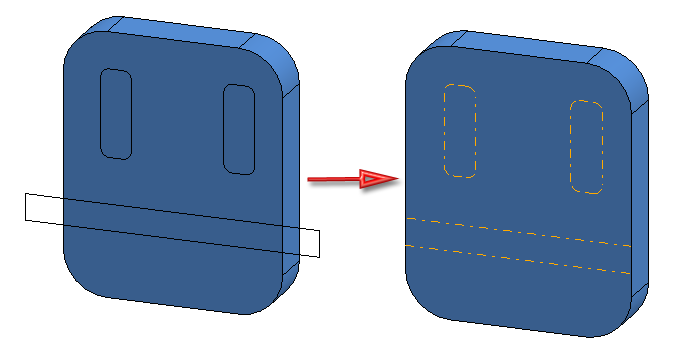
By activating this option you can apply the lines of a sketch as powder marking lines to a part. The sketch lines must be located on the surface of the part and will, where necessary, trimmed to the surface, i.e. projecting lines will not be applied as powder marking lines. If the Delete after creation checkbox is active, the sketch will be automatically deleted after creation of the powder marking lines. Please note that sketch elements which have been defined as auxiliary geometries will not be applied as powder marking lines.
Make the desired settings and confirm with OK. The further procedure depends on the selected mode.
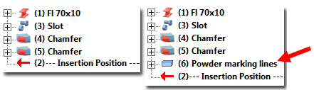
For each powder marking line search, a feature called Powder marking lines will be created for the feature log of the part onto which the lines have been projected. If you have selected the Selected parts mode, such an entry will be created for each identified, attached part (provided that any powder marking lines exist).
If no powder marking lines could be found, the message No powder marking lines created. will be displayed.
Example 1:
In the example below, the powder marking line search for the assembly main part (1) was performed automatically. Parts 2 and 3 create (cause) the powder marking lines.
Feature log before and after powder marking line search
Example 2 - Using a sketch
In the image below the lines of a sketch have been applied to the part as powder marking lines.
Example 3 - Applying powder marking lines to part lists
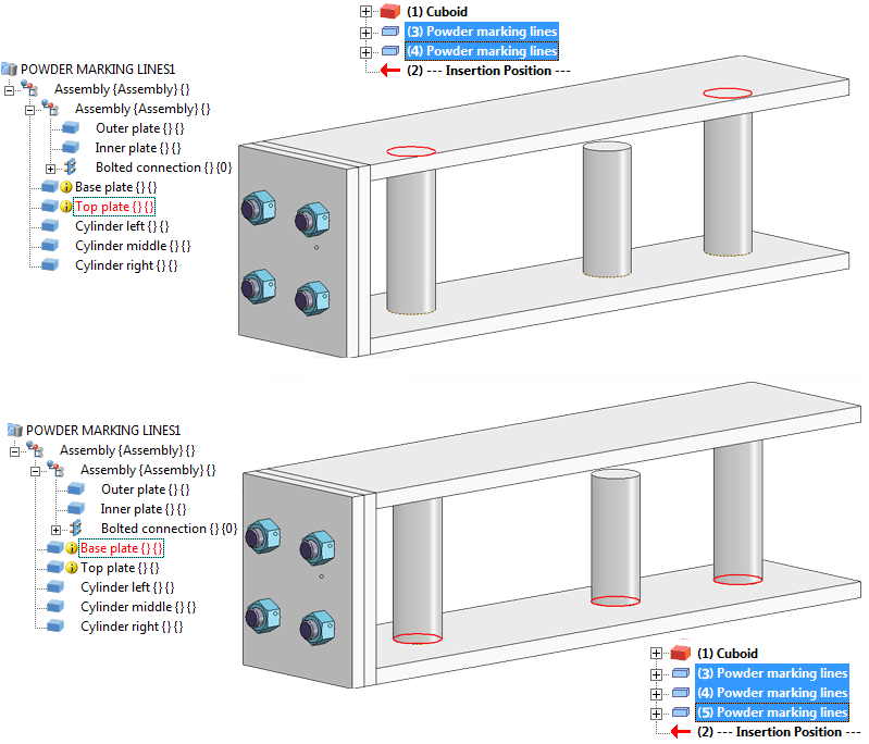
In the example below the Base plate and the Top plate have been selected before calling the function. In the Selected parts mode, the Cylinders (1) , (2) and (3) have then been selected.
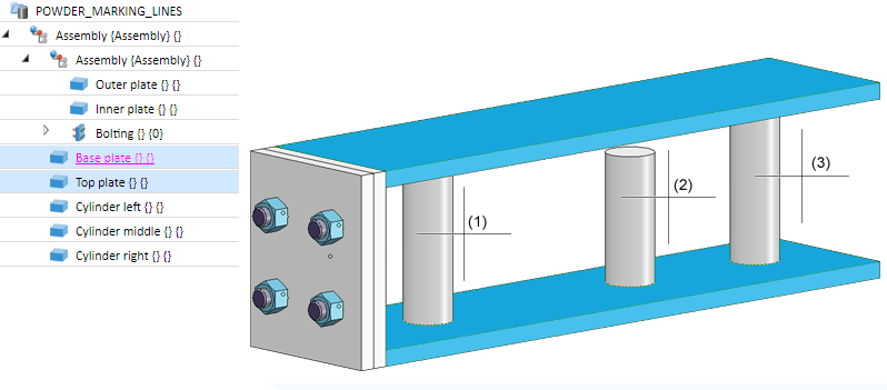
HiCAD will then automatically detect the powder marking lines caused by the cylinders on the base plate and the top plate.
Example 4 - Powder marking lines in Sheet Metal parts
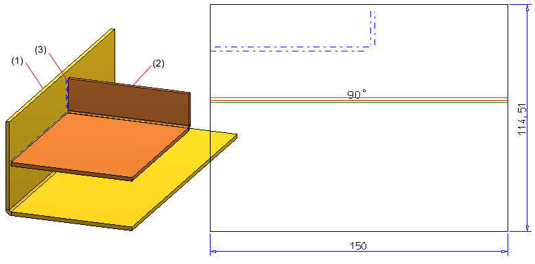
(1) Active Sheet Metal main part (1), (2) Selected Sheet Metal main part, (3) Powder marking lines
 Please note:


|
© Copyright 1994-2019, ISD Software und Systeme GmbH |