Project: HiCAD 3-D
Extrude Cross-Section
3-D FFS > From c-edge > Extrude cross-section 
This function creates a freeform surface by moving a curve (cross-section) along a vector and connecting the original curve with the moved curve. The curve for the cross-section (Sketch or 3-D Sketch) needs to exist in the drawing already.
All required entries can be made via the dialogue window of the function.
Proceed as follows:
- Click the Select cross-section
 icon and identify the cross-section in the drawing.
- Click the Direction of translation
 icon and determine the displacement vector, either by specifying of two points or by identifying an edge.
- Determine the height of the moving. The Start height will be the start distance and the End height the end distance of the part to the sketch plane, respectively processing plane.
- Parts can directly be referenced when they are created, if you activate the Referenced checkbox.
- Enter the part name.
- Activate the Preview button to display a preview of the part. You can then either modify the entered values or insert the displayed part into the drawing by clicking the Apply button. When clicking the Create button the part will be inserted immediately.

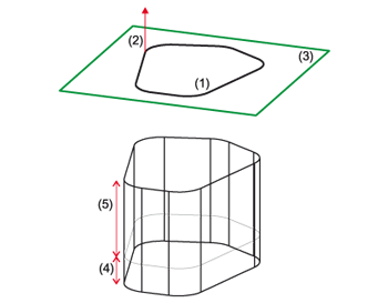
(1) 3-D sketch, (2) Displacement vector, (3) Sketch plane, (4) Start height, (5) End height
 Please note:
- The options Preview, Cancel, Create and Apply can also be selected via a context menu. You activate this menu with a right-click outside the input window.
- If a preview is already shown, it will, in case of any changes made in the input fields, only be updated if you confirm these changes with ENTER.
- To connect the curve and its copy, proceed as you would with the Surface via connection function. In the process, one NURB surface is created from each pair of connected edges. The individual freeform surfaces are, topologically speaking, not connected with each other!


FFS from C-Edge (3-D FFS) • Overview of Functions (3-D FFS) • Freeform Surfaces
|
© Copyright 1994-2019, ISD Software und Systeme GmbH
Version 2402 - HiCAD 3-D
Date: 06/10/2019
|
> Feedback on this topic
|


 icon and identify the cross-section in the drawing.
  icon and determine the displacement vector, either by specifying of two points or by identifying an edge.
![]() Please note:
Please note: