> 3-D Grid
Project: HiCAD 3-D
Drawing > Others > Extras > 3-D Grid
Grids are an important construction aid for 3-D design.
The properties of a 3-D line grid:
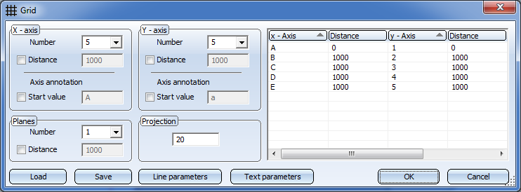
The Grid dialogue window is displayed to enable you to configure steel engineering grids.
|
Options and Buttons |
|
|---|---|
|
Number |
Number of grid lines in x-/y-direction |
|
Distance |
For even axis distances, enter the distance between the axes in the Distance field. If you want the distances between the axes to be uneven, you can enter the values directly into the table on the right-hand side of the window. |
|
Axis annotation |
An axis annotation will always be created; if the checkbox has been activated here, you can enter a start value for a consecutive axis annotation. If you do not want the axis annotation to be consecutive, deactivate the checkbox and enter the axis annotation directly in the table on the right hand side of the dialogue window. |
|
Planes |
3-D grids can consist of several planes. Specify the Number of planes and the Distance between each of the planes. |
|
Projection |
This value determines how far the grid lines will project beyond the border of the grid. |
|
Line parameters |
Click this button to specify the parameters for the grid lines. The Line parameters for 3-D grid dialogue window will be displayed, enabling you to select the colour, line type and layer of the grid lines. |
|
Text parameters |
Click this button to specify the text parameters for the axis annotation. The Text parameters dialogue will be displayed, enabling you to select the colour, layer size, font etc. of the axis annotations. |
|
Save |
Click this button to save the current grid settings. The data is saved in the HiCAD subdirectory Makro 3-D/Raster under the specified name with the extension .RST. The RST files can be reused at any time – even for other steel engineering constructions. |
|
Load |
Click this button to load a saved 3-D grid (.RST). |
If you have made the desired grid settings, choose OK to exit the window. HiCAD displays a preview of the grid.
To position the grid exactly:
You can define so-called Grid sub-systems to refine the structure of 3-D grids or a Steel Engineering grids. Different sub-systems can be created on the various planes of the grid, and can also run diagonally to them. A grid sub-system consists of a start point and an end point and is represented as an edge. Along this refined grid, constructions can be erected, and the corresponding beams can be placed. You can find the function in the context menu for grids. You open the context menu by right-clicking the grid
![]() Please note:
Please note:
 called Grid. For each level of the grid, a sub-part named Grid (Type=part with free edges) is assigned to the main part.
 . Here, the Isolated points checkbox needs to be active.
  Settings > Grid annotations to annotate the grid axes individually. In addition, you can apply the 3-D dimensioning functions to grids if desired.

|
© Copyright 1994-2019, ISD Software und Systeme GmbH |