 > ...
> ... Project: HiCAD 3-D
3-D Dimensioning + Text > Text > Leader > ...
Click to open a menu with functions for the editing and processing of part annotations:
|
|
|
|
|
|
|
|
|
|
|
|
|
|
|
|
|
|
|
|
|
|
|
|
|
|
|
|
|
|
|
|
|
|
|
|
|
|
|
|
|
In the context menu of an annotation you will find the function
|
|

3-D Dimensioning + Text > Text > Leader > Edit, Edit 
You use this function to edit existing annotations. It enables you to change the composition of the annotation texts and the display of the annotation.
The annotation is adjusted accordingly.
![]() Alternatively, you can open the Annotation settings window by double-clicking on an annotation..
Alternatively, you can open the Annotation settings window by double-clicking on an annotation..
3-D Dimensioning + Text > Text > Leader > Edit, Move 
You use this function to move the leader line of an annotation.
![]() Please note:
Please note:
3-D Dimensioning + Text > Text > Leader > Edit, Delete
The following deletion options are available:
|
|
Delete, Individual Deletes individual annotations (by means of identification) |
|
|
Delete, in rectangle Deletes all annotations within one or several selection rectangles. The annotations will only be deleted after a right-click. |
|
|
Delete, Only active part Deletes all annotations of the active part |
|
|
Delete, Active view Deletes all annotations of the active view |
|
|
Delete, Entire drawing Deletes all annotations of the drawing |
3-D Dimensioning + Text > Text > Leader > Edit, Change font
You use this function to change the text parameters of an annotation. The following options are available:
|
|
Change font, In rectangle Changes all fonts lying within a drawn rectangle. |
|
|
Change font, only active part Changes all fonts of the active part |
|
|
Change font, Active view Changes all fonts of the active view |
|
|
Change font, Entire drawing Changes all fonts of the drawing |
Choose the desired function and then, in the dialogue window, define the parameters for the annotation texts and the item number. You can set font, colour, height and line spacing. The Delete selected text block button deletes the contents of the fields.
![]() The default settings for font, colour and line type of
annotations as well as the spacing of the text lines are defined in POS3DPARNEU.DAT
in the SYS directory. To change these during the HiCAD session, use the
Settings, Global function.
The default settings for font, colour and line type of
annotations as well as the spacing of the text lines are defined in POS3DPARNEU.DAT
in the SYS directory. To change these during the HiCAD session, use the
Settings, Global function.
3-D Dimensioning + Text > Text > Leader > Edit, Clone 
Use this function to copy annotations of one part to other parts. Simply identify the part to which you want to assign a clone of the selected annotation.
![]() When moving annotations in model drawings with multiple views, the target point always refers to the original view
When moving annotations in model drawings with multiple views, the target point always refers to the original view
3-D Dimensioning + Text > Text > Leader > Edit, Show/Hide in view
These functions enable you to show/hide annotations of a view. You can select whether you want to hide or show particular annotations, all annotations of a view, or all annotations of the active view.
|
|
Show in view, individual |
|
Hide in view, individual |
|
|
Show in view, active part |
|
Hide in view, active part |
|
|
Show in view, all |
|
Hide in view, all |
3-D Dimensioning + Text > Text > Leader > Edit, Optimise arrangement 
Use this function to optimise the positioning of all annotation tags and 3-D texts in the active view in one step. In the new, optimised positioning there will be no collisions and overlaps of annotations, dimensionings or 3-D parts.
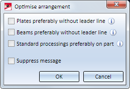
For plates and beams you can determine -analogously to the Automatic part annotation - whether the annotations for beams and plates are to be applied with or without leader line.
If this checkbox is active, HiCAD proceeds as follows: If there is enough space on the part, the annotation for the plate will be placed directly on the part. If there is not enough space, the annotation will be created with a leader line.
If this checkbox is active, HiCAD proceeds as follows: If there is enough space in the vicinity of the part, the annotation will be placed along the beam as shown below. If there is not enough space, the annotation will be created with a leader line.
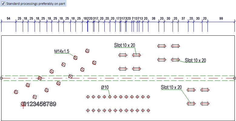
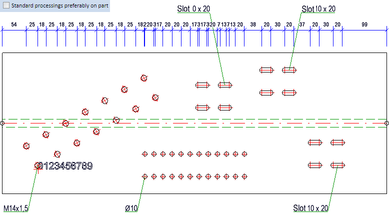
If the checkbox is active, the annotations of standard processings are placed directly next to the processing, i.e. on the part, if there is sufficient space. If there is not enough space, the annotation will be placed a little farther. If the checkbox is deactivated, the annotations will be placed outside the part. For example, this may result in annotations running through bore patterns or dimensions. This is the ISD default setting.
An example:
The last specified settings that have been confirmed with OK will be the default settings when the function is called again.
3-D Dimensioning + Text > Text > Leader > Settings, Replace text 
Use this function to find and replace text strings of an annotation.
Enter the search string and the string to be replaced, and start the process with OK.
RMB > Insert base point 
Use this function to add additional leader lines to a part annotation. These leader lines have no own text block and always end at the text block of the selected part annotation.
The function is only available in the context menu of part annotations.
Right-click on the part annotation for which you want to add further leader lines, and choose Insert base point.
Then, determine the reference point of the additional leader line. The line will be drawn from the text block of the selected annotation to the selected point. The start point of the additional leader line depends on the orientation of the selected part annotation (Reference/Insertion point), i.e. on the type of the selected complete frame.
![]() Please note:
Please note:
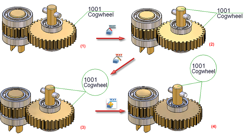
(1) Part with annotation; (2) Annotation with additional leader line, the base point is the centre of the frame; (3) Changed annotation settings; (4) Moving of annotation

Texts and Annotations (3-D) • Part Annotation (3-D)
|
© Copyright 1994-2019, ISD Software und Systeme GmbH |


