Project: HiCAD 3-D
3-D-Standard > Process with sketch > Deform
Use this function to deform parts by bending them along a defined sketch. The following types of deformation are available:
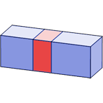
The sketch plane determines the neutral axis for the deforming process. This means that the part area to be deformed is determined by the planes (2) and (3) that are vertical to the start point and end point of the sketch (1):
Proceed as follows:
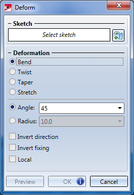
The Deform dialogue window will be displayed. In the drawing, the selected part will be highlighted in green colour.
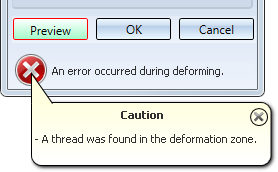
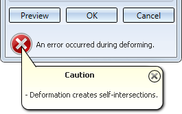
If mandatory specifications are still missing, the  symbol will be displayed at the bottom of the window. If you move the cursor on the symbol, a message informing you which steps are still necessary before the function can be executed.
Sketch
Click the  icon and identify the sketch for the wrapping in the drawing. The sketch needs to fulfil the following criteria:
If a correct sketch has been identified, the Identify sketch prompt will be replaced by the entry Sketch.
Deformation
In this area you define the type of deformation by activating the corresponding checkbox. Depending on the selected type, the input fields and available options in the dialogue window will change.
You can choose between the following options:
| Deformation | Available modes |
|---|---|
|
Bend |
The bending can be performed by specifying the
|
|
Twist |
Angle |
|
Taper |
Factor |
|
Stretch |
The stretching can be performed by specifying either the
If you specify the Distance, the area to be deformed will be stretched/compressed in such a way that it will have the width you specified for Distance. |
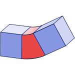
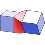
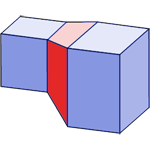
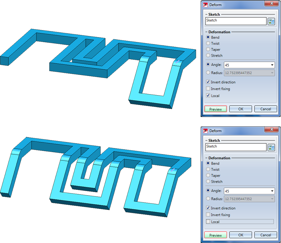
When you move the cursor over the different options in the dialogue window, preview images will be displayed:
|
|
|
|
|
|
Bend |
Twist |
Taper |
Stretch |
Invert fixing
By default, the part area that lies before the start point of the sketch will remain fixed during deforming. The Fixing checkbox enables you to switch the fixing to the exact opposite of the part.
Invert direction
By default, the part will be bent in Z-direction of the sketch in the deforming process. You can use the Direction checkbox to invert the bending direction. This can be applied in a similar way to deformations of the type Twist. Here, the rotation is performed about the X-axis of the sketch. Here, too, you can use the Direction checkbox to invert the rotation direction.
Local
As already mentioned, the selected sketch determines two planes running perpendicular to the axes at the start/end. If the Local checkbox has been deactivated, (default), everything will be deformed that lies between these two planes. Activating the checkbox allows the selection of a local deformation. In the vicinity of the corresponding axis it will then be attempted to select the smallest possible area from all the areas/connected elements of the part that are located between the two planes, and apply the deformation only there.
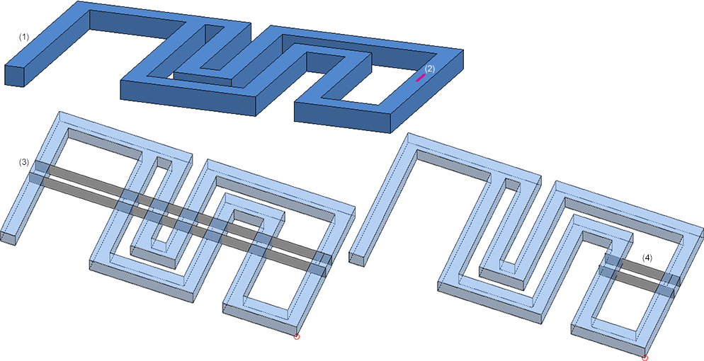
(1) Part to be deformed; (2) Sketch; (3) Planes - Checkbox Local deactivated; (4) Planes - Checkbox Local activated
The next image shows the difference after a deformation:
 Click here to view an example of local bending.
The following deformation options are available:
|
Deformation |
Options |
||
|---|---|---|---|
|
Invert |
Invert |
Local |
|
|
Bend |
|
|
|
|
Twist |
|
|
|
|
Taper |
|
|
|
|
Stretch |
|
|
|
Click the Preview button to show a preview of the deformed part in your drawing. You have now the following options:
Click OK to perform the deformation.
(1) Original part with sketch; (2) Bend angle 30°, (3) Direction checkbox active, Fixing checkbox inactive; (4) Direction checkbox inactive, Fixing checkbox active
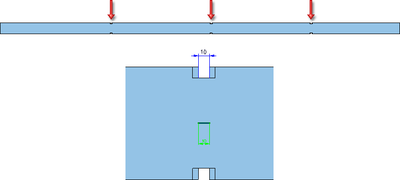
In the image below the sketch has been slightly moved. As a result, the form of the bore will also change in the deformation process:
(1) Original part with sketch; (2) Top view, (3) Deformed part
(1) Original part with sketch; (2) Twisting 90°, (3) Tapering with factor 1.2
(1) Original part with sketch, (2) Stretching, factor 2
Please note:
symbol on the OK button.

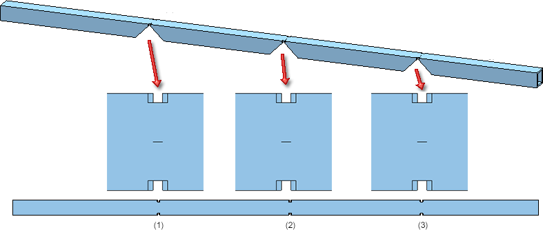
The following example shows how local bending work in practice. The image below shows the original part (1) and the desired result (2). (3) shows an enlarged view of the "inflexion area".
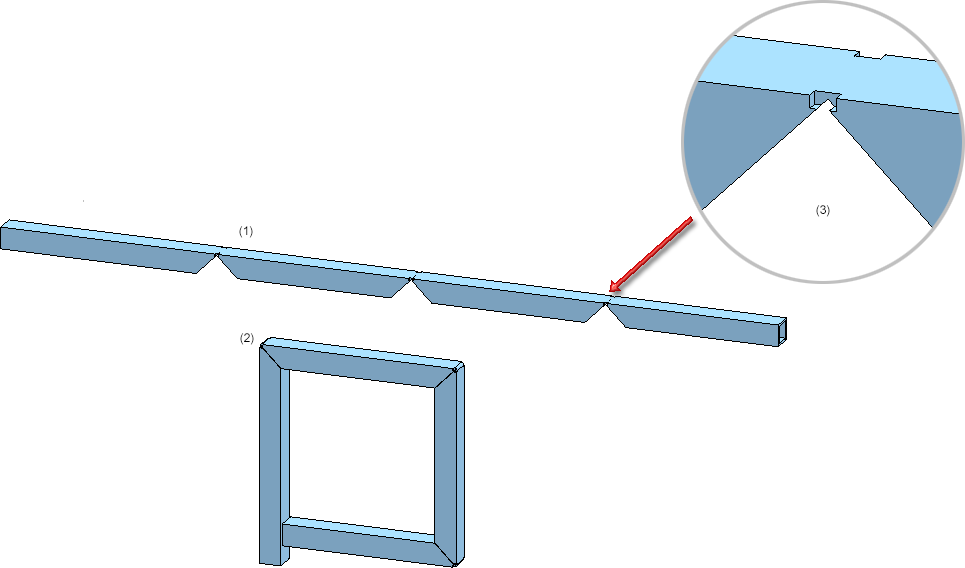
To achieve this result, use the Bend option here. Then, create three sketches in the "inflexion areas" that have exactly the length of the recesses:
The bending is carried out in the three steps, in the order as shown below:
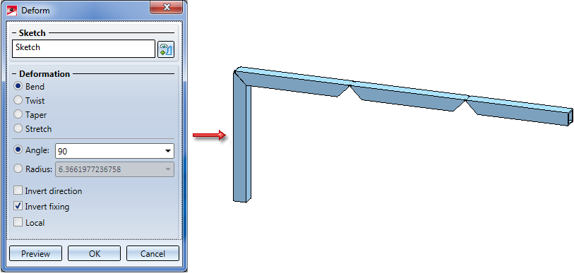
Step 1:
Select the Sketch for area (1). The left area is to be bend 90 degrees in downward direction. Therefore, activate the Invert fixing checkbox here. Otherwise, the other areas would be bent in downward direction.
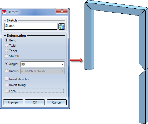
Step 2:
Select the Sketch for area (2). A bending of 90 degrees is to be applied. No other options need to be activated here, as local and global bending would lead to the same result here.
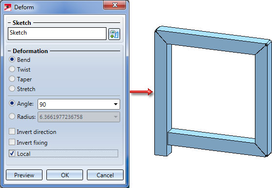
Step 3:
Select the Sketch for area (3). A bending of 90 degrees is to be applied. Here you must activate the Local checkbox to achieve the desired result. If you do not activate the checkbox, the entire part would be bent, i.e. the area bent in Step 1 would be bent back again, leading to an unwanted result.

Transform and Clone Part (3-D) • Transform Part (3-D) • Referencing (3-D)
|
© Copyright 1994-2019, ISD Software und Systeme GmbH |