Project: HiCAD 3-D
The image below shows a contour that is to be used in different sizes for the creation of bore patterns. It can either be created and parameterized as a 2-D part or as a planar sketch.
Case 1: Parametrized 2-D part (File format: .DCF)
Case 2: Parameterized sketch (File format: .KRA)

Step 1: Create the 2-D part
 and place an isolated point in the centre of that rectangle.
Step 2: Derive the 2-D HCM model
 > Delete variables
  . > Parallel
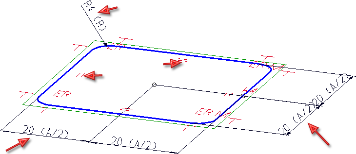
  to determine the parallelism constraints. After calling the function, first identify the two vertical lines, and then the two horizontal lines.
 function to assign the same-named positional constraint to the elements: Identify, one by one, a line and an arc, so that you end up having a total of 8 tangential constraints.
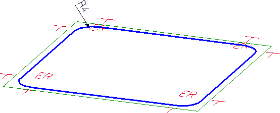
> Equate radius  for the non-dimensioned fillets.
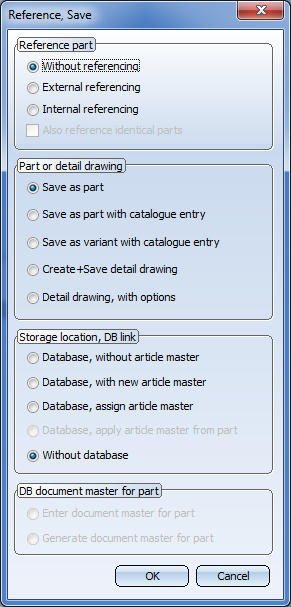
  .> Without database
  , e.g. with the name PATTERNEXP. Select the HiCAD directory KATALOGE/WERKSNORMEN/MUSTERBOHRUNGEN as the target directory.
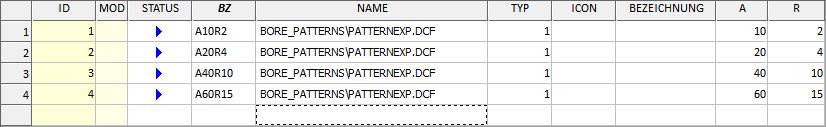
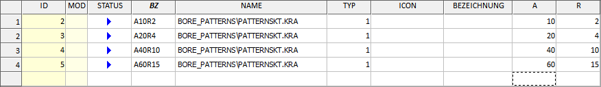
Expand the MUSTERBOHRUNGEN catalogue
|
Designation |
Data type |
Comment |
|
|
NAME |
Text |
Path of HCM model |
|
|
A |
Float |
Lateral length of square |
|
|
R |
Float |
Fillet radius |
Step 1: Create the sketch
 and create a new sketch.
  function.
  function (Radius: 4).
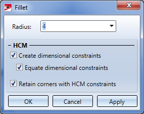
 . Place an isolated point in the centre of the square. Call the New point number
  in the pull-down menu of the Point function to assign the point number ! to this point. Via this point number you can influence the fitting point during insertion of parts and assemblies.
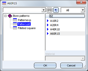
 function, e.g. with the name PATTERNSKT, to the HiCAD directory KATALOGE/WERKSNORMEN/MUSTERBOHRUNGEN.
Step 2: Expand the MUSTERBOHRUNGEN catalogue
|
Designation |
Data type |
Comment |
|
|
NAME |
Text |
Path of KRA file |
|
|
A |
Float |
Lateral length of square |
|
|
R |
Float |
Fillet radius |

Bore Patterns (3-D) • Standard Processings (3-D) • Variable Through Holes (3-D) • Repeated Insertion of Standard Pats (3-D)
|
© Copyright 1994-2019, ISD Software und Systeme GmbH |