
"Civil Engineering functions" docking window > Civil Engineering, general > Civil Engineering - Sectional views (3-D) > Foil
A prerequisite for this function is the existence of an active 3-D sectional view.
Within this sectional view, create a Sketch with the edge contour along which you want to place the foil. If no sketch exists in the cut plane after calling the Foil function, it will be immediately created (HiCAD will prompt you to select the start point).
The Foil dialogue window with various Fitting options will be displayed:
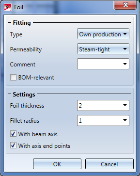
Activate the same-named checkbox if you want the foils to be BOM-relevant.
In the Settings area of the window you can specify the Foil thickness and the Fillet radius , and, if desired, exclude the beam/profile axis and axis end points from the representation by deactivating the corresponding checkboxes.
After confirming with OK , HiCAD will prompt you to specify the insertion direction of the foil.
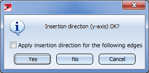
Click Yes if the displayed insertion direction is correct, or click No to display a different direction. If you activate the Apply insertion direction for the following edges checkbox, the following edges will obtain the same direction. Otherwise the dialogue will be displayed again for these edges.
After selecting the insertion direction the foil will be inserted into the cut plane and subsequently shown in your drawing.


|
© Copyright 1994-2018, ISD Software und Systeme GmbH |