Feature Technology - Clone Processings
3-D-Standard > Process > Clone processings 

Clone processings
The Clone processings function allows you to apply one or several processing steps in the feature log multiple times, i.e. the processing will be "cloned", so to speak. You can call the function either via 3-D Standard > Process > Clone processings  , or by right-clicking a feature log entry and selecting "Clone feature".
When you call the function, the following dialogue window will be displayed:
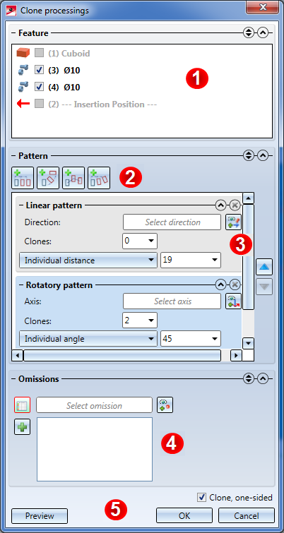
(1) In this area, the features of the active part are listed. Use the checkboxes preceding the features to select the features you want to clone. If a feature is greyed out, it cannot be cloned. If y feature is highlighted in blue, you need to perform a recalculation before you can clone the feature.
The following processing steps can be cloned:
- Add, via translation / rotation
- Subtract, via translation / rotation
- Fillet and Chamfer
- Boolean operations: Add, Subtract, Difference
- Some, but not all Standard Processings
- Rotate surface
- Isolated point
- Deform: Bend, Twist, Taper, Stretch
- Appearance (e.g. colour of surface)
- Move edges
- Crosshairs
- Wrap
- Fitting CS
- Attach flange
(2) Use these buttons to add various patterns for the clonings.
The following cloning patterns are available:
-
 linear patterns,
-
 rotatory patterns,
-
 linear + rotatory patterns ,
-
 polyline patterns
-
 mirror transformations.
You can also add several patterns, which will then be applied one after the other.
(3) In this area the added patterns are displayed and can then be modified or deleted.
(4) In this area you can define Omissions.
(5) Click the Preview button to switch the preview of the cloned features on or off. Use the Clone, one-sided checkbox to activate or deactivate the option to apply clonings also in the opposite displacement or rotation direction.

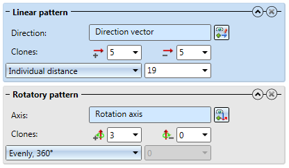
Linear pattern
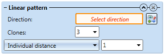
- Direction: Here you specify the direction in which the displacement is to take place. This vector can be selected via 2 points, 1 edge or 1 plane.
- Clones: Here you specify how many times the features are to be repeated; if the Clone, one-sided checkbox is deactivated, both in positive and in negative direction.
- Length input field: Select the type of distance between the features. The following options are available:
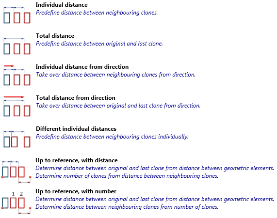
- Individual distance: Specify the distance between 2 clones.
- Total distance: Specify the complete distance (i.e. the distance from the "first" to the "last" clone); the remaining clones will be evenly distributed.
- Individual distance from direction: Same as "Individual distance", with the difference that the length of the direction vector will be used as the distance value.
- Total distance from direction: The complete distance of all clones corresponds to the length of the direction vector; the remaining clones in between are evenly distributed.
- Different individual distances: Specify the distance of each individual clone to the next clone.
- Up to reference, with distance: Specify the distance of the clones, as well as a reference length via selection of 2 points and an (optional) offset. HiCAD will then calculate the length of the reference length minus the offset and distribute the clones up to this length with the specified distance along the initially selected direction.
- Up to reference, with number: Like Up to reference, with distance, with the difference that the distance of the clones will be determined by the specified number and the length of the reference length.

Rotatory pattern
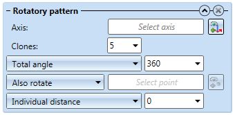
- Axis: Here you specify the axis for the rotation.
- Clones: Here you specify the number of clones of the feature; if the Clone, one-sided checkbox is deactivated, both in positive and in negative direction. .
- Rotation angle input field:
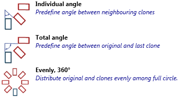
- Individual angle: Each clone will be rotated by the given angle with regard to the previous clone.
- Total angle: The specified value is the complete angle between the "first" and the "last" clone. The remaining clones in between are evenly distributed.
- Evenly, 360°: Arranges the clones evenly in a 360° circle.
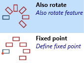
- Also rotate: Rotates the feature as well.
- Fixed point: The selected fixed point will also be rotated and the feature to be cloned will be placed with its original alignment.
- Individual distance: Each clone will be moved in the direction of the rotation axis by the value you specify here.
- Total distance: The clones will be moved in the direction of the rotation axis in such a way that the original feature and the last clone will have the specified distance and the features in between are distributed at equal distances.

Polyline pattern
- Polyline: Here you select the polyline along which the clones are to be placed. You can also create a new sketch here. Please note that the sketch may only contain one polyline.
- Start value or Start point:
- Start value input: Here you specify the distance of the first clone from the start of the polyline.
- Start point selection: Select a point in the sketch on which the first clone is to be placed. This point needs not necessarily be located in the sketch. If the point is located outside the sketch it will be projected onto the sketch.
- Alignment:
- No fixing: The clones will follow the polyline in their rotation.
- Fixed point: If you use this option, the clones will first applied in the same way as with the "No fixing" option, but then rotated about the chosen fixed point to regain their original rotation.
- Fixed direction: Define a direction in the sketch. During clone creation the feature will only be rotated about the axis given by the direction, but not about other axes.
- Clones: Here you specify the number of clones for the feature. If the Clone, one-sided checkbox has been deactivated, the clones will each be created in positive and negative direction.
- Distance:
- Individual distance: Here you specify the distance between two clones.
- Total distance: Here you specify the complete distance (i.e. from the first to the last clone), the remaining clones will be distributed at equal distances.
- Total distance from polyline: The length of the polyline will be determined and used as total distance value.
- Different individual distances: Opens a table where you can enter the distances per clone.
Examples showing the effect of the "Fixed point" alignment type
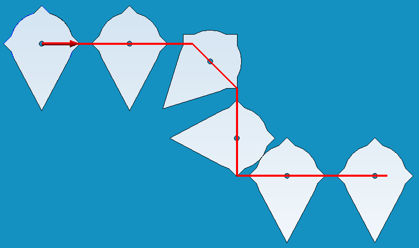
"Original position": "No fixing"
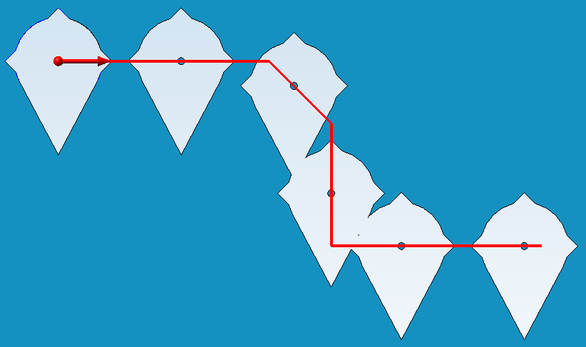
Fixed point in the middle of the marker.

Normal "No fixing"
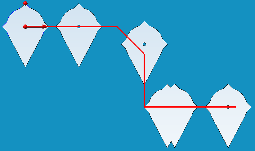
Fixed point at the upper "spike"
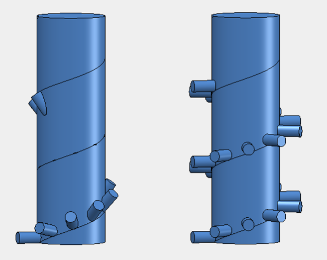
Cloned attachment along a spiral. Left: Without fixed point; Right: With fixing direction along centre axis of the large cylinder

Translatory and rotatory pattern
The translatory and rotatory pattern combines a linear pattern with a rotatory pattern. In the process, the direction vector of the linear movement will be rotated before the displacement for each clone.
- Direction: Here you select the direction of the displacement. This vector will also be rotated.
- Clones: Here you specify the number of clones for the feature. If the Clone, one-sided checkbox has been deactivated, the clones will each be created in positive and negative direction.
- Distance:
- Individual distance: Here you specify the distance between two clones.
- Total distance: Here you specify the complete distance (i.e. from the first to the last clone); the remaining clones will be distributed at equal distances.
- Individual distance from direction: Same as "Individual distance", but with the difference that the length of the direction vector will be used as distance value.
- Axis of rotation: Select the axis for the rotation. This axis will also be moved during the translatory displacement.
- Angle:
- Individual angle: Starting from the previous clone, each clone will be rotated by the specified angle
- Total angle: Here you specify the complete (i.e. angle between the first and the last clone); the remaining clones will be evenly distributed in between.
- Evenly, 360°: Arranges the clones evenly in a 360° circle.

Mirror transformation

- Mirror plane: Choose the plane on which you want to mirror the selected processings.

Multiple clonings
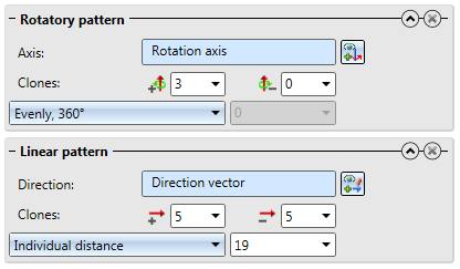
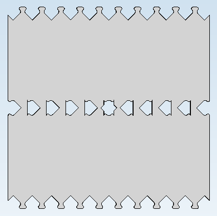
If you specify several patterns for a cloning action by means of the Clone processings function, they will be applied in the order in which they were defined. Patterns that are defined later will then no longer only affect the one original processing, but also the processings created by the processings created by the previous patterns. Therefore, the result of the function also depends on the order of the processings.
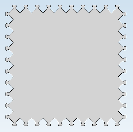
One example is the plate with one subtraction. The subtraction is to be cloned linearly along the upper edge, and rotatorily about the centre of the plate.
The original situation with direction vector and rotation axis looks as follows:
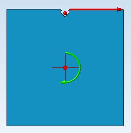
If you first apply the linear pattern, and then the rotatory pattern, you will obtain the desired result:
If you change the order of patterns, the result will look completely different:

Omissions
In the Omissions area you can specify individual clonings that are to be omitted. To do this, click on the Select omission button (1) and then identify individual omissions in the drawing (2).
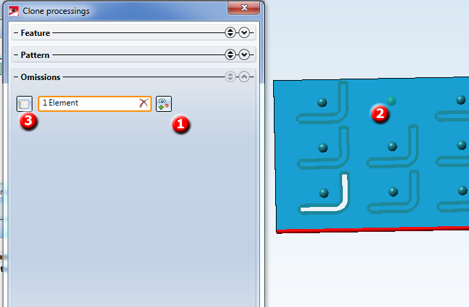
Alternatively you can click Show table (3) button show the omissions in tabular form.
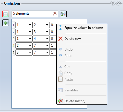
One column will be displayed per defined cloning pattern. One row stands for one omission. You can add further omissions by clicking the Plus button.
You can right-click an entry of the table to open a context menu that offers, besides common functions such as Undo or Copy / Paste, some other functions:
- Equalize values in column: Copies the value of the clicked entry to all entries in the same column.
- Delete row: Deletes the row of the clicked entry.
- Variables: Opens a window with the variables assigned to this object, which can then be applied to this entry.
- Delete history: Clears the history of previous values shown in the drop-down menu of an entry.
Example:
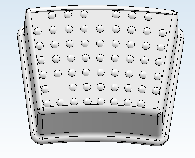
The anti-slip nubs on this stool were cloned on the basis of the nub in the bottom left area - first, linear to the top, and then rotatory to the right.
The following omissions were defined:
1, 1 for the missing nub at the bottom left area (1st cloning of the linear pattern, 1st cloning of the rotatory pattern), 6, 0 for the missing nub in the top left corner (6th cloning of linear pattern. 0th cloning of rotatory pattern), - likewise:
6, 4 and 6, 8 for the further nubs in the upper row and 0, 8 for the nub in the bottom left corner.

Further notes
- During entering of distances or angles you can right-click the input field to open a context menu with further functions:
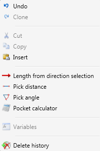
This allows you to apply the length of the specified direction vector as lengths, or pick distances and angles directly from the drawing.
 Please note:
- If you select the Individual distance from direction or Total distance from direction option for a linear pattern, the length of the direction vector will be shown in the Length field. This value can then no longer be changed and will be highlighted in yellow.
- The Clone processings function shows no error messages if not all clonings can be performed (e.g. because an edge to be filleted does not exist). In the feature log, this feature will however be marked with an exclamation mark.
- As subsequent processings may be a hindrance to a proper creation of clonings, it is recommended to perform the clonings via the feature log immediately after the original processing.
- If very many clonings are to be created, this can slow down or even prevent previews. However, the cloning of the feature will still take place.
- If several processings are to be cloned these will be completely dealt with in succession. One example for this is a subtraction with filleted edges: First, the subtraction will be cloned as often as desired, and then, the edges are filleted. In case of overlapping subtractions, however, this may prevent the detection of the edges to be filleted.

|
© Copyright 1994-2018, ISD Software und Systeme GmbH
Version 2302 - HiCAD Feature Technology
Date: 14/09/2018
|
> Feedback on this topic
|


 , or by right-clicking a feature log entry and selecting "Clone feature".
 linear + rotatory patterns ,
 polyline patterns
  mirror transformations.


 Please note: