 > Flanges to surface
 Sheet Metal > Attach > Flange  > Flanges to surface
 ![]()
For the attaching of a flange to a surface, the following 4 options are available:
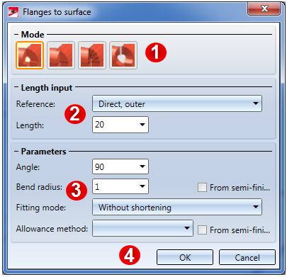
Lengths and parameters are specified in the same way for all 4 variants.
You can enter a value for the desired length. If you right-click the Length input field, a context menu with further options opens. You can then, for example, choose Pick distance to take the length directly from the drawing.
You have the following options to define the reference of the length:
|
|
Direct, outer Flange length up to intersection point of outer flange surfaces |
(1) new flange |
|
|
Direct, inner Flange length up to intersection point of inner flange surfaces |
(1) new flange |
|
|
Direct, to outer tangent Flange length up to outer bend zone surface |
(1) new flange |
|
|
Direct, to inner tangent Flange length up to inner bend zone surface |
(1) new flange |
|
|
Outer distance Vertical distance of end of new flange, measured from the outer flange surfaces |
(1) new flange |
|
|
Inner distance Vertical distance of end of new flange, measured from the inner flange surfaces
|
(1) new flange |
The bend angle can either be entered in the Angle input field or taken from the drawing by right-clicking the Angle input field and selecting Pick angle.
The Bend radius is located at the inner side of the bend zone. If you right-click the Bend radius input field you can directly pick the radius from the drawing. If the checkbox beside Bend radius is active  , and the Use semi-finished product checkbox had also been activated
  in the Base sheet dialogue window, the radius will be loaded from the catalogue.
The Fitting mode refers to the processing of the connecting sheet. The following possibilities are available:
To obtain the blank (development) of the modelled Sheet Metal part, HiCAD offers you developments according to different calculation methods (allowance methods) that take the material-dependent length change of the workpiece during bending processes into account. For this, HiCAD also offers the common empirical, practice-oriented allowance methods.
The calculation methods are represented by prepared, exemplary system files. In practice, however, each user will store his own method(s) in this way. Before attaching the flange you can select the required system file.
Bend zone free ![]()
Use this function to attach flanges around a surface (base sheet). The selection of the top surface determines the direction of the new flanges.
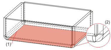
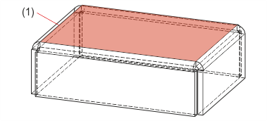
(1) Top surface
(2) Flange with free bend zone
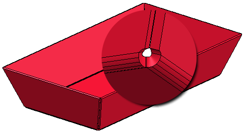
Bend zone closed ![]()
Use this function to attach flanges with closed bend zones around a surface (base sheet). Sheets and bend zones will be lengthened up to the common intersection point of the inner edge. The selection of the top surface determines the direction of the new flanges.
Drainage area ![]()
Use this function to attach flanges with drainage area around a surface (base sheet). The selection of the top surface determines the direction of the new flanges.
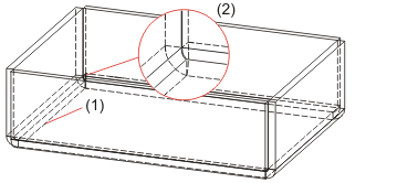
(1) Top surface
(2) Flanges with drainage area
Circular ![]()
Use this function to attach flanges with a circular cut-out around a surface (base sheet). The selection of the top surface determines the direction of the new flanges.

Attach Flange (3-D SM) • Close Corner (3-D SM)
|
© Copyright 1994-2018, ISD Software und Systeme GmbH |