 > Along sketch
 Sheet Metal > Attach > AlongSkt  > Along sketch
 ![]()
Use sketch technology to attach several flanges around a sheet in one step.
The flange is added taking the corresponding technology data into account. Use the Technology data menu to change pre-set technology data.

(1) Sketch
(2) Connecting point in sketch
(3) Reference surface
The flange is constructed, according to the sketch, in negative x-direction. Before identifying the reference surface, right-click to rotate the sketch into positive x-direction.

(4) Sketch, in negative x-direction
(5) Sketch, rotated with a right-click

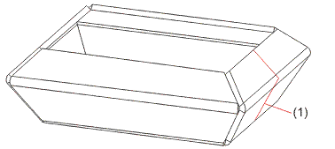
(1) Sketch after insertion
As in this example a bend angle of 60° has been entered for the technology data, the first flange is bent outwards.
 Please note:
Instead of specifying the connecting point you can use the right mouse button to take over the position of the sketch, provided that the sketch lies on the connecting edge.

|
© Copyright 1994-2018, ISD Software und Systeme GmbH |