Plant Engineering > Guideline Tools > Create guideline > ... Settings
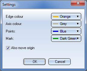
Besides defining the colour settings for edges, axes points and markings you have the option to influence the position of the grid via the Also move origin checkbox.
 Also move origin
The axes origin for graphic specification of the next guideline point is placed in a point, whose coordinates are constituted by integral multiples of the grid size and which is located as closely as possible to the previous guideline point (on new workstations this is the default setting for the creation and processing of guidelines).
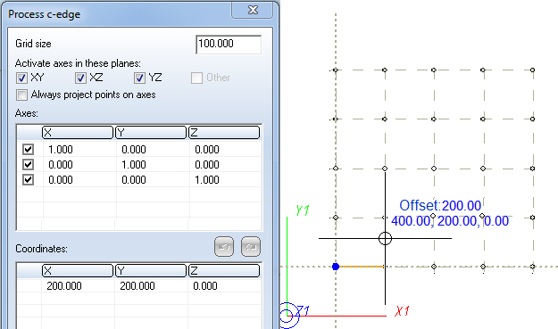
If the axes origin is not located in the previous point, the direction of the edge to the next point in the grid will deviate from the axis direction.
 Also move origin
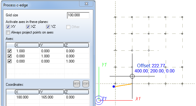
The axes origin for graphic specification of the next guideline point is placed in the previous guideline point.
If the previous point is located in a grid point, there will be no difference to a setting with deactivated Also move origin option.
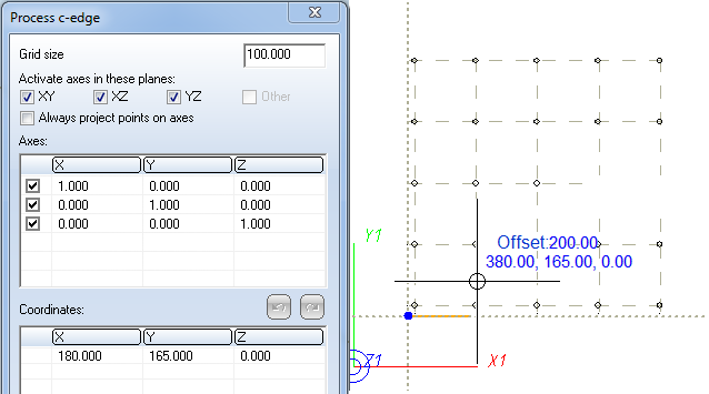
If the previous point is not located in a point of the current grid, the grid will be moved in such a way that the previous point will be located in a grid point afterwards. The coordinates of the grid points will however continue to refer to the currently valid coordinate system.
The edge to the next point (set by a left-click) now runs in axis direction. The grid points shown in the image represent the grid before performing the displacement.
 The default values in the Settings dialogue window can be determined in the Configuration Editor at Plant Engineering > C-edge > Representation.


Guideline Tools (PE) • Plant Engineering Functions
|
© Copyright 1994-2018, ISD Software und Systeme GmbH |