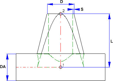
Saddle connection (Example)
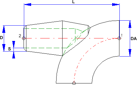
Elbolet (Example)
D=Outer diameter of the nozzle, DA=Outer diameter of the part to which the connection is made, L=Length, S=Wall thickness
Rules for the creation of individual Plant Engineering parts
|
|
|
|
|
Saddle connection (Example) |
|
Elbolet (Example) |
|
D=Outer diameter of the nozzle, DA=Outer diameter of the part to which the connection is made, L=Length, S=Wall thickness |
||
Please note that the variable DA (Outer diameter) will be modified upon insertion. It will be applied to the outer diameter of the pipe to which the connection is made. This allows the calculation of the part geometry to match the respective fitting situation. Please check whether the geometry of the constructed saddle connection correctly adjust itself to a modified DA value.
Named isolated points
|
Designation |
Purpose |
Comment |
Position in coordinate system |
|---|---|---|---|
|
! |
Connecting point |
Fitting point |
in origin (0,0,0) |
|
2 |
Connecting point |
|
X = 0, Y = 0, Z > 0 |
Required attributes for entries into database or catalogue
The entering of attribute values and the part type selection should be performed using the PAA Editor.
Values need to be entered for at least the following attributes:
|
Attribute |
Description |
|||||||||||||||||||||||
|---|---|---|---|---|---|---|---|---|---|---|---|---|---|---|---|---|---|---|---|---|---|---|---|---|
|
BENENNUNG |
Designation of part |
|||||||||||||||||||||||
|
NORMBEZEICHNUNG |
Standard designation of the part. An entry is mandatory, even if the part corresponds to no standard. |
|||||||||||||||||||||||
|
|
|
|||||||||||||||||||||||
|
NENNWEITE |
Nominal diameter, Connection “!“ and “2“ |
|||||||||||||||||||||||
|
|
|
|||||||||||||||||||||||
|
Additionally (only if the corresponding standard uses nominal diameters in inches): |
||||||||||||||||||||||||
|
NPS_INCH |
Nominal diameter (inches) (e.g. 1 1/2‘', the '' consists of two '' characters), Connection“!“ and “2“ |
|||||||||||||||||||||||
|
|
|
|||||||||||||||||||||||
| These sizes are to be considered for all connection types except for the flange connection. For sockets they refer to the pipe to be inserted: | ||||||||||||||||||||||||
|
D_AUSSEN |
Outer diameter of the part to which the connection is made. This allows a suitable adjustment of the nozzle. |
|||||||||||||||||||||||
| D2_AUSSEN | Outer diameter of the nozzle, Connection “!“ and “2“ | |||||||||||||||||||||||
|
WANDDICKE |
Wall thickness, Connection “2“ |
|||||||||||||||||||||||
|
|
|
|||||||||||||||||||||||
|
ANSCHLUSSART
ANSCHLUSSART2 |
Connection type for Connection “!“(and “2“) If the same connection type is required at both part ends it will suffice to assign a value to the attribute ANSCHLUSSART. If different connection types are required at the part ends you need to assign the value of the connection type for Connection 1 to the attribute ANSCHLUSSART, and the connection type for Connection 2 to the attribute ANSCHLUSSART2. |
|||||||||||||||||||||||
|
Possible values of the attributes ANSCHLUSSART (CONNECTION_TYPE) and ANSCHLUSSART2 (CONNECTION_TYPE2):
The last character (x) provides information about the meaning of the supplement: 0 =No supplement 2 = The supplement consists of connection number, part type, ID, and standard of the part to be connected The prefixed connection number indicates the connection with which the auxiliary part is to be attached to the current connection.
|
||||||||||||||||||||||||


Creating Individual Parts: Procedure (PE)
|
© Copyright 1994-2018, ISD Software und Systeme GmbH |
 Please also read the information given in the paragraphs