Pipeline Isometry from Layout Plan (PE)
Plant Engineering > Isometry / Pipe Spool Drawing > Linked documents
If a layout plan has been loaded, you can use the pipeline isometry and pipe spool drawing function Linked documents to display and load the isometry and pipe spool drawing documents which are linked to it via the database.
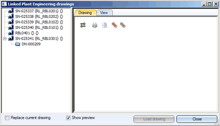
In the above example, isometry documents were not assigned to all pipelines.
The preview window
When you click on the document number of the isometry document, the assigned graphic is displayed in the Drawing tab on the right-hand side of the window, provided that the Show preview checkbox is active (default setting).
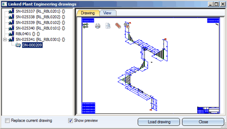
The Drawing tab provides the following functions for isometry documents:
Toolbar functions
Hide/Show toolbar
View all
Show all parts
Show only active part
Print
Context menu functions
You activate the context menu by right-clicking the preview window.
- View all
Displays the current file as large as possible.
- Show all figures
Redisplays all hidden parts of the isometry.
- Hide figure
Hides the selected part in the isometry. Select the desired part with a left-click first, then activate the context menu with a right-click, and then call the function.
- Print
Prints the current file in colour.
- Print (B/W)
Prints the current file in black + white.
- B/W mode
Displays the preview window with white background if the option is active, otherwise the background colour set below is used.
- Background colour
Assigns a background colour to the preview window.
Mouse button functions, Keyboard shortcuts
- Left mouse button
- Select parts with a left-click
- Draw rectangular zoom window: Set first corner point with a left-click, hold down the left mouse button and draw the rectangle by moving the mouse.
- Middle mouse button (mouse wheel)
Zoom by scrolling the mouse wheel
- CTRL key+ middle mouse button
View all
- CTRL key+ right mouse button
Move object in the preview window
Please note:
- For very large drawings, the loading of the preview may take a little longer. In such cases you can switch off the preview function by deactivating the corresponding checkbox.
- If isometry documents are selected, the View tab will be empty.
- If you want to view the linked isometry or pipe spool drawing of a particular pipeline, you may also directly identify a part of this pipeline with a right-click and select the Linked documents function in the context menu. You will then get the same window as described above; however, only the documents for this pipeline will initially be shown in the list of the pipeline names (the tree structure is only expanded for this particular pipeline name). The graphic for the first isometry or pipe spool drawing document linked to the pipeline will be displayed.
Loading of isometry and pipe spool drawing documents
If you want to load an isometry or pipe spool drawing for processing, select the document on the right hand side of the window and select Load drawing. By default, the document will be loaded to a new HiCAD window, while the layout plan will remain open. If you do not want this, activate the Replace current drawing checkbox.
Isometry and Pipe Spool Drawing (PE/Iso) • Isometry and Pipe Spool Drawing Functions for the Layout Plan • Plant Engineering Functions
© Copyright 1994-2018, ISD Software und Systeme GmbH Version 2302 - HiCAD Plant Engineering Date: 11/07/2019
|
> Feedback on this topic
|