Rules for the creation of Feature Variants for Plant Engineering parts

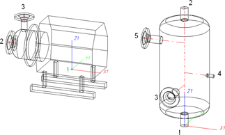
Named isolated points
|
Designation |
Purpose |
Description |
Position in coordinate system |
|---|---|---|---|
|
! |
Connecting point or auxiliary point |
Fitting point |
in origin (0,0,0) |
|
2, 3, 4 etc., unambiguous within the part |
Connecting points or auxiliary points |
|
arbitrary |
Connecting points should preferably be created via the Component connection function, or (for various components) by the insertion of nozzles.
Each component connection (and the fitting point, if it is an auxiliary point) needs to be located in a plane belonging to the part. It needs however not be located within the surface boundary.
Example:

|
If the connecting point is located in the plane of the ring surface, the surface condition is fulfilled. Caution: It would also be fulfilled if the point would be located in the same plane, but outside of the ring. |
To assign an unambiguous orientation to a connection, a connecting point must not fulfil the surface condition for several surfaces at once.
VAA file
Use the Variant Editor to enter the suitable part type into the VAA file.
Then, use the Variant Editor to expand the VAA file in such a way that appropriate attributes such as HOEHE (HEIGHT), BREITE (WIDTH), LAENGE (LENGTH) etc.are assigned to the individual variables, enabling a distinguishing between various sub-types during part selection.
For variant synchronization you also need to enter the values for the attributes which are to apply to all sub-types of the variant.
Values must be entered for at least the following attributes:
|
AttributE |
Description |
|---|---|
|
BENENNUNG |
Designation of the part |
|
COMPONENT_TYPE |
Part type (always = Semi-finished material+Plant Engineering) for HELiOS database only |
|
NORMBEZEICHNUNG |
Standard designation of the part (identical for all sub-types!) An entry is mandatory, even if the part corresponds to no standard. |

Rules for the Creation of User-Defined Parts (PE)
|
© Copyright 1994-2018, ISD Software und Systeme GmbH |