
3-D part
Symbolic representation
Symbolic representations are required for parts or part variants that are used for pipelines of which you want to generate isometries. You use the Symbol Editor to draw such symbolic representations.
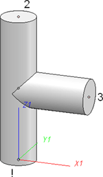
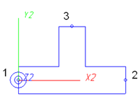
Below please find the example of a T-piece:
|
|
|
|
3-D part |
Symbolic representation |
The symbolic representation is drawn in the Symbol Editor  as a 2-D part in the XY-plane.
The Z-axis in the 3-D part corresponds to the X-axis in the symbolic 2-D representation. The 3-D X-axis corresponds to the 2-D Y-axis.
The symbolic representation needs to contain (just as the 3-D part) named isolated points indicating the positions of connections or auxiliary points. The point "1" in the symbolic representation is located in the origin of the coordinate system and corresponds to the point "!" in the 3-D part. Points "2" and "3" correspond to the same-named points in the 3-D part.
There are only two parts that require a point "4" in their symbolic representations, namely Branch and Y-piece (the 4-way valve contains no point "4").
|
|
|
|
Example: Branch |
Example: 4-way valve |

Creating Individual Parts: Procedure (PE) • Creating New Part Variants: Procedure (PE)
|
© Copyright 1994-2018, ISD Software und Systeme GmbH |