Plant Engineering > Part Tools > Move points 
This function is identical to the same-named 3-D function at 3-D Standard > Process > MovePts, that enables you to model 3-D parts by moving individual points.
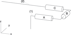
This function is very useful if you want to modify the layout of a pipeline. The following example is intended to demonstrate the function. Let us assume that a guideline was drawn and parts placed as shown below:

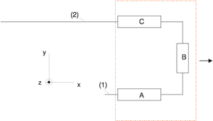
Now, let us assume that you need more space to the left of part A, in order to insert another part between part A and the guideline corner. In other words: You want to lengthen the guidelines (1) and (2) to the right, and also move the U-shaped section to the right of (1) and (2) together with its parts A, B and C in X-direction.
Proceed as follows:


Part Tools (PE) • Plant Engineering Functions
|
© Copyright 1994-2018, ISD Software und Systeme GmbH |