3-D Standard > > Extruded solids 
You use this function to create general cylinders. They are derived from closed sketches by moving a copy of the sketch along a normal.
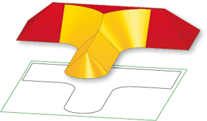
Particular mention deserves the automatic processing of self-intersections. The image below shows an extruded solid derived from a sketch with self-intersection processing. The "oblique" surfaces were created as draughts of the extruded solid; the other, highlighted surfaces would contain self-intersections without an appropriate processing. After self-intersection processing has been applied, they end well below the cover surface and can be extended up to the cover surface via (cut) edges if required.

Recommended procedure:
To create an extruded solid, proceed as follows:
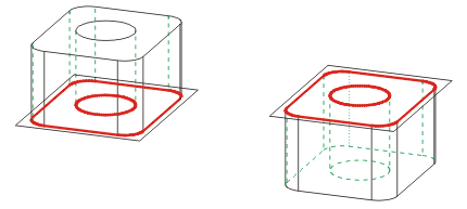
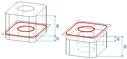
The images below show extruded solids, generated with different values for draughts, start height and end height.


Left: Start/End height: 0/80  Height of part: 80; Right: Start/End height 0/-80
  Height of part: 80

Left: Start/End height: -20/80  Height of part: 100; Right: Start/End height -20/-80
  Height of part: 60

Left: Start/End height: 20/80  Height of part: 60; Right: Start/End height 80/0
  Height of part: 80 (part "inverted")
Please also read the notes on the purposes and representation of sketches.
![]() Please note:
Please note:
 and select Create new extruded part as sub-part
 .
.  function to sketches first.
  ... opens a pull-down menu with the functions 2-D -> 3-D Conversion
  und 2-D -> 3-D Level -> Body
  .
.

New Sketch (3-D) • Dialogue Window for Extruded Solids
|
© Copyright 1994-2018, ISD Software und Systeme GmbH |