Revolved Solids (3-D)
3-D Standard > New > Revolved 
Revolved solids are created from sketches by cloning and rotating
them about an axis lying in the screen plane.
On activating this function, the New revolved solid dialogue window is displayed.
Recommended procedure:
- Enter the Article number.
- Activate the
Referenced checkbox if you want the revolved solid
to be referenced.
- Activate the
Feature checkbox if you want a corresponding feature
of this revolved solid to be included in the feature log.
- Activate the BOM-relevant checkbox in order to automatically assign this attribute to the created revolved part.
- Choose theType. Revolved
solids can be created as entire bodies or segments.
- Enter the Start angle
and End angle for segments.
- Under Sketch for cross-section, choose the type
of cross-section definition. You can create
a new sketch or use a sketch that already exists in the drawing.
- Specify the Rotation
axis.
- If you first
want to check what the created part looks like, click the Preview button, followed by Apply if you want the part to be created as displayed. If you want the part
to be created directly – without a preview –, click Create.
The revolved part will be inserted as main part into the drawing.

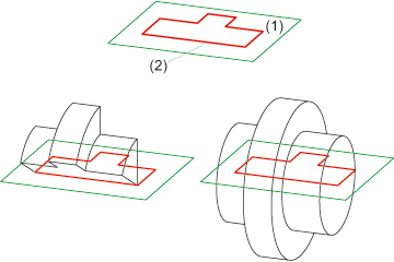
Revolved solid - as segment and and complete body, (1) Sketch, (2) Rotation axis
Please also read the notes on the purposes and representation of sketches.
 Please note:
- If you want to insert the revolved part as sub-part to the active part, click
 and select Create new revolved solid, as sub part
 .
.
- It is recommended to apply the Sort
GE (sketch)
 function to sketches first.
- Internal cycles, i.e. closed polylines, circles and ellipses lying within a sketch
area, are interpreted as cut-outs/bores.
- Circular cross-sections
produce toruses.
- Revolved bodies can
only be created as analytical bodies. Ellipses and ellipse arcs are exceptions.
- The rotation axis
must not intersect the sketch and always lies in the screen plane.
- HCM dimension conditions
assigned to the sketch are taken over as parametric dimensions.
- If a preview of the
revolved solid is displayed, it is only updated, in the case of changes
to the values in the input fields, if you confirm the value input by pressing
ENTER.
- If the sketch already exists, you can also use the Revolved part from sketch function in the context menu of the sketch to create the revolved part. Please note the following: If the sketch belongs to an assembly, the resulting revolved part will also be assigned to this assembly.


Dialogue Window for Revolved Solids • New Sketch • Part Creation Functions (3-D)
|
© Copyright 1994-2018, ISD Software und Systeme GmbH
Version 2302 - HiCAD 3-D
Date: 30/10/2018
|
> Feedback on this topic
|


![]() Please note:
Please note:  and select Create new revolved solid, as sub part
 .
.  function to sketches first.