 > Transition curve
Sketch > Draw > Freehand  > Transition curve
Use this function to automatically create a curve with a moderated curvature (Hermite spline) between 2 points.
After selecting the function, HiCAD will prompt you to specify the first connecting edge or the start point of the curve.
First connecting edge or start point
First connecting edge
If you want to determine the start of the created curve via a connecting edge, identify the desired edge. The edge end point that is closest to the identification will be used as start point. The direction of the curve will then be determined by the outward direction of the tangent.
Identification of the start point
If you want to explicitly specify the start point of the curve, identify the desired point. After you have specified the start point, HiCAD will prompt you to specify the direction.
First point, line or plane for direction
You can do this via specification of two points for the direction vector, via identification of a line or via identification of a plane.
Specify the start point, and then the end point of the direction vector. You can select the origin of the active part or of the active processing plane via the context menu (right-click).
Identify the desired line. The direction of the curve will then be the direction of the line. You can select the coordinate axes of the active part or of the active processing plane as the direction.
Identify a plane. The direction will then be determined by the plane normal.
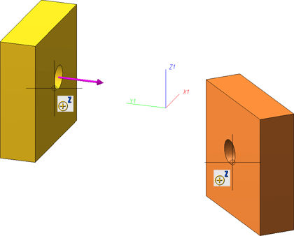
After you have defined the start point and the direction of the curve, HiCAD will display a graphical representation of the direction vector, and prompt you to specify the second connecting edge or the end point of the curve.
Second connection edge or end point
Proceed in the same way as for the specification of the first connecting edge or the start point. Before you identify the second connection edge, HiCAD will show you, when you move the cursor near an edge, a preview of the curve that would be created upon identification of this edge
While the function is activated you can right-click to open a context menu with further options. The functions offered in the menu depend on whether HiCAD prompts you to specify a point or identify an edge, or prompts you to determine the direction via First/Second point, line or plane for direction.
|
|
|
|
Specify point/edge |
Determine direction |
Use the Origin option to place the next specified point into the origin of the current coordinate system. This can be the World CS or the Part CS, or -if a processing plane is active - the origin of the coordinate system defined by the processing plane. If you want to undo one or several steps of the process in order to make corrections, select the Step back option (if required, several times). Select Cancel if you want to abort the function. In the context menu for direction specification you will find additional functions enabling you to apply the X-, Y- or Z-direction of the current coordinate system.
Upon completion of your entries, HiCAD generates a Hermite spline from the first point to the last point.
Example
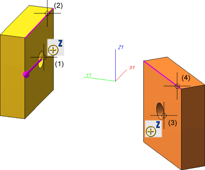
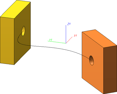
In the example below a transition curve is to be generated from the centre of the bore in the left cuboid to the centre of the bore in the right cuboid:
(1) Start point, (2) Line for direction, (3) End point, (4) Line for direction

Result

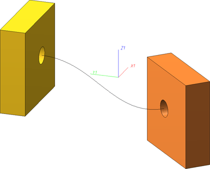
The screenshot below shows the same example. Here, however, the centre points of the bores were selected as start and end point. The direction was determined by the corresponding facet with the bore.

Result

 Please note:

3-D-Sketch (3-D) • Sketch Functions (3-D)
|
© Copyright 1994-2018, ISD Software und Systeme GmbH |