Processing plane 
Use this function to create a new processing plane. Please note that the definition of a processing plane always entails the definition of a local coordinate system!
After calling the function, HiCAD prompts you to specify a plane, a surface, an edge or a point. You can then use, in an arbitrary order, points, edges, surfaces and also already existing processing planes, for the definition of a processing plane in your drawing, or right-click to open a context menu with further functions for processing plane creation.
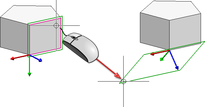
As soon as a suitable input position has been created ( the X-direction has been specified, or a plane has been selected) a dynamic preview consisting of a coordinate system and a plane frame, will be displayed. This allows you to see what would happen after the next mouse click.

Dynamic preview
|
Identification type |
Meaning |
|---|---|
|
Point, Point, Point |
The first point is the local zero point, the second point is a point on the X-axis and the third point is a point on the Y-axis. |
|
Point, Point, Edge |
The first point is the local zero point, the second point is a point on the X-axis. The edge determines the Y-axis. |
|
Point, Edge, Point |
The first point is the local zero point, the edge determines the X-axis and the last point is a point on the Y-axis. |
|
Point, Edge, Edge |
The point is the local zero point. The first edge determines the X-axis, the second edge determines the Y-axis. |
|
Point, Point, Plane |
The first point is the local zero point. The second point determines the direction of the X-axis (positive/negative) The processing plane runs parallel to the selected plane and through the first point.
|
|
Point, Edge, Plane |
The first point is the local zero point. The edge determines the direction of the X-axis (positive/negative). The processing plane runs parallel to the selected plane and through the selected point. |
|
Point, Parallel plane |
The first point is the local zero point. The processing plane runs parallel to the selected plane and through the selected point.
|
|
Edge, Point |
The edge determines the X-axis, the point is a point on the Y-axis. |
|
Edge, Edge |
The first edge determines the X-axis. The local zero point is the end point of the edge that is closest to the cursor position. The second edge determines the orientation of the Y-axis. The query for the second edge will be omitted if the first edge is a circle or an ellipse! In this case the centre point is the local zero point, and the quad point that is closest to the cursor position will determine the X-direction.
|
|
Edge, Parallel plane |
The edge determines X-axis. The local zero point is the end point of the edge which is closets to the cursor position. the processing plane runs parallel to the selected plane and through the local zero point. |
|
Surface |
The processing plane is placed in the selected plane. The local zero point depends on the cursor position.
When selecting a cylinder or cone, the processing plane will be placed in the quad plane which is closest to the cursor.
If you select a plane as surface, circles and ellipse are handled in a special way:
|
After the first selection of a point, an edge, a surface or a plane, you can right-click to open a context menu with further options:

|
Perpendicular to line/direction This function is only available if the X-direction has not been defined yet. If, for example, you have selected one point as the local zero point, and one edge for the X-direction, this function will not be available in the context menu. If the X-direction has not been defined yet, you can use this function to place the processing plane perpendicular to a line/direction. HiCAD will prompt you to specify the Z-direction by selecting a line or two points.
(1) Specification of local zero point, (2) Right-click and select "Perpendicular to line/direction" function, (3) Select line, (4) Preview examples |

|
Origin The direction of the X- or Y-axis, respectively, is determined by the origin of the active coordinate system. |

|
Step back If you want to correct your input, select this function (multiple times if required). |

|
Cancel (ESC) Cancels the function. |
![]() Please note:
Please note:
 symbol on the transparent toolbar.

Processing Planes (3-D) • Move/Rotate Processing Plane (3-D)
|
© Copyright 1994-2018, ISD Software und Systeme GmbH |