 .
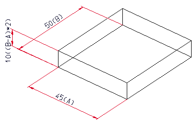
.In many cases, HiCAD automatically generates parametric dimensions for sizes when creating and modelling parts. This applies, for example, to solid primitives or extruded solids, but also to chamfers and fillets as well as to material subtractions or bores. HCM dimension conditions assigned to a 3-D sketch are also adopted as parametric dimensions.
You can change the visualisation of parametric dimensions via 3-D Standard > Tools > Part attributes > Visualisation, Parametric dimensions .
.
By default, parametric dimensions are visible if the corresponding feature step of a part is active.
To process a parametric dimension, right-click the dimension. Next, a context menu containing the relevant processing functions is displayed. The functions are identical with the same-named functions for 3-D dimensions.
For parametric dimensions, the additional Change feature parameters  function is available to the user, provided that a feature log exists. Use this function to quickly and conveniently change the dimensions of a part and include the changes in the feature log:
 function.
 Instead of a value, you can also use variables – known as part variables. To do this, enter the name of the variable and then in its initial value.
If desired, parametric dimensions can also show the variables/formulas contained in the feature items. This is possible for parametric dimensions of solid primitives, extruded solids, revolved solids, standard bores, fillets and chamfers. Default setting is Dimension figure+variable/formula

Parametric dimensions with dimension figure and formula
You can change the default setting via the Configuration Editor ISDConfigEditor.exe. To do this, select ... > Drawing > Annotations > Dimensioning, 3-D > Show formulae in parametric dimensions.
![]() Please note:
Please note:
 . Here, you can show parametric dimensions
in sheet views, as well as hiding and deleting them in particular views.
 function to influence the representation of parametric dimensions. You can access this function via 3-D Dimensioning + Text > Tools > Dimension
 .
.  > Settings.

Dimensioning Tools (3-D) • Part Attributes (3-D)
|
© Copyright 1994-2018, ISD Software und Systeme GmbH |