2-D Part > Standard Parts > Weld seams
Weld seams are defined by means of:
In the case of weld seams acc. to DIN 7912, the following weld symbols are available:
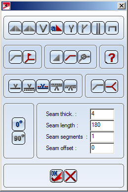
Once you have called the function, the selection menu is displayed:
1st button row
The first row of the menu contains a selection of different weld symbols. The currently active symbol is highlighted in colour.
You can change the configuration of this line.
 function from
the 2nd line.
function from
the 2nd line. A selection with other weld symbols is made available.
The symbol that was active when you chose the Further weld seams function is replaced in the 1st line by the newly selected symbol.
2nd button row
In this row, you choose type and form of the weld symbol.
3rd button row
In the third row, you define the type of reference line.
In addition, you can define here whether you want the weld seam to be created in accordance with ISO 4063 or not.
Bottom area
In the bottom area of the menu, you choose the angle of rotation and enter the parameter values for the weld seam.
DIN does not allow you to enter any angles you like.
After insertion, the weld seam menu opens, and you can create other weld seams.
(1) Reference point for arrow
(2) Start point for reference line
(3) Symbol
(4) Thickness
(5) Length


|
© Copyright 1994-2018, ISD Software und Systeme GmbH |