HELiOS Attributes in Drawing Templates
All document, article, folder and project master attributes that have been defined in HELiOS can be displayed in AutoCAD.
The configuration of this transfer takes place via system files.
Further down this page you will also find some important notes about drawing frames and title blocks and the creation of templates.
System files
The transfer takes place via two configuration files which can be found in the \sys\ directory of the HELiOS installation: heliosac_titleblock.dat and helacblock.xml.
The heliosac_titleblock.dat file determines which HELiOS attributes are to be read out. One attribute can be defined per line.
Below you will find an example showing you how such lines should look:
 Example: heliosac_titleblock.dat
<DATA>
...
"HELPRT_BENENNUNG";"30,B.BENENNUNG";
"HELDOC_BENENNUNG";"30,D.BENENNUNG";
"HELPRO_NR";"30,P.HEL_PROJNUMMER";
...
"HELDOC_INDEX1";"2,D.HEL_INDEX[1:8]";
"HELDOC_INDEX1_TEXT";"55,D.Indextext[1:8]";
"HELDOC_INDEX1_DATE";"12,D.Indexdatum[1:8]";
"HELDOC_INDEX1_NAME";"12,D.Indexname[1:8]";
...
<DATAEND>
The first line item defines under which name the attribute in the file helacblock.xml is to be transferred, e.g. HELPRT_BENENNUNG. The name can be chosen freely.
The second item, separated by a semicolon, is the definition of the HELiOS attribute to be transferred, e.g. 30,B.BENENNUNG.
The value 30 indicates the number of characters to be transferred. B, D, M and P stands for part, document, folder and project master attributes. BENENNUNG (=DESIGNATION) is the real name of the HELiOS attribute.
Concerning the indication of the revision indices, please note the following: Here you need to specify how many last indices are to be indicated, and which of them is to be addressed, e.g. HEL_INDEX[1:8]
In the above example, the first of the last 8 indices will be shown. If, for example, a document has 10 indices, the third one will be shown as the first.
The file helacblock.xml transfers the attributes that were read out of HELiOS to AutoCAD.
Below you will find an example of how this file is to be composed:
Example: helacblock.xml
<AcadProperties>
...
<Block Name="ISD SCHRIFTKOPF">
...
<Attrib HelName="HELPRT_BENENNUNG" Name="PRT_BENENNUNG" Value="" />
<Attrib HelName="HELDOC_BENENNUNG" Name="DOC_BENENNUNG" Value="" />
<Attrib HelName="HELPRO_NR" Name="PROJEKTNUMMER" Value="" />
...
<Attrib HelName="HELDOC_INDEX1" Name="INDEX1" Value=""/>
<Attrib HelName="HELDOC_INDEX1_TEXT" Name="INDEX1_TEXT" Value="" />
<Attrib HelName="HELDOC_INDEX1_DATE" Name="INDEX1_DATE" Value="" />
<Attrib HelName="HELDOC_INDEX1_NAME" Name="INDEX1_NAME" Value="" />
...
</Block>
...
</AcadProperties>
For each AutoCAD block (e.g. the title block) to be considered, one node has to be inserted here. The attribute Name contains the block name. Please note that these entries are case-sensitive!
<Block Name="ISD SCHRIFTKOPF">
In this node, all attributes to be considered are listed:
<Attrib HelName="HELPRT_BENENNUNG" Name="PRT_BENENNUNG" Value="" />
HelName is the name of the Helios property specified in the heliosac_titleblock.dat file. If this Helios property exists, this block will be used and adjusted accordingly. Name is the attribute name in the AutoCAD block. Value is the attribute value assigned to the AutoCAD attribute, before the (optional) Helios value is entered.

Drawing frames and title blocks
The drawing frame is to be created in the model area of AutoCAD and can be saved as a separate DWG file. In this way it can be inserted as a block into the AutoCAD template.
The title block can also be saved as a separate DWG file (e.g. ISD TITLE-BLOCK.DWG) and, like the drawing frame, inserted into the AutoCAD template.
The file name will later be the basis for the block name; therefore, it needs to correspond to the entry in the configuration file helacblock.xml, e.g.:
<Block Name="ISD SCHRIFTKOPF">
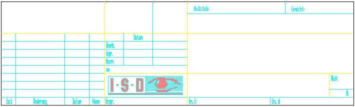
In this title block the AutoCAD block attributes need to be defined in which the HELiOS attributes are to be displayed.
To enter a block attribute in AutoCAD, select Draw > Block > Define Attributes*.
Tag* determines the AutoCAD designation of the attribute that was specified in the helacblock.xml file. Prompt* defines the display when the block is inserted. Default* is the default text shown in AutoCAD.
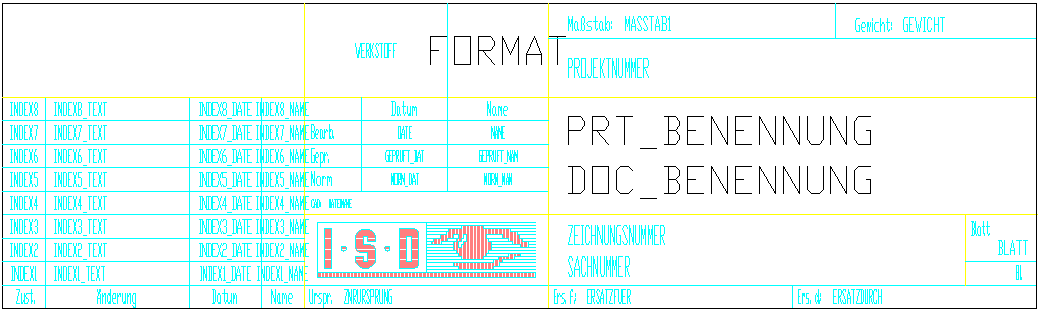
After defining, formatting and positioning of all attributes, the title block could look as shown below:
* Note: The exact menu structure paths and command names in AutoCAD may vary, depending on the version.
Templates
The templates for AutoCAD 2014* have the extension DWT* and are normally located at
%Localappdata%\Autodesk\AutoCAD Mechanical 2014\R19.1\eng\Acadm\Template*.
If you want to adjust this path, select Tools > Options > Files > Template Settings > Drawing Template File Location*.
To create a new template, you can either use a new file without template (e.g. File > New > Open > Open with no Template- Metric* ) or an existing template and adjust it accordingly.
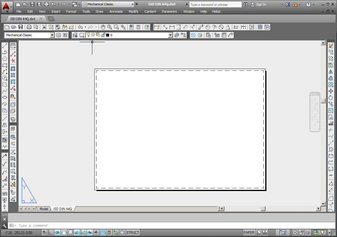
After creating the template you can, for example, save it under the name ISD DIN A4Q.dwt.
Now you need to adjust the layout. Select File > Page Setup Manager > Modify* in AutoCAD to display the settings for the corresponding layout.
Depending on the printer you use, several settings such as size, orientation, etc. can be specified here. Further details on how to adjust the page layout can be found in the AutoCAD documentation.
After defining the page layout, the prepared drawing frame and title block files can be inserted as blocks and positioned: Select Insert > Block > Browse*. It makes sense to create individual layers for these blocks.
Finally, insert a view window. This can either be done via the Viewports* toolbar, or via View > Viewports*.
* Note: The exact menu structure paths and command names in AutoCAD may vary, depending on the version.
|
© Copyright 1994-2018, ISD Software und Systeme GmbH
Version 2302 - HELiOS PDM for AutoCAD
Date: 30/10/2018
|
> Feedback on this topic
|