![]()
![]()
Note on updatesWhen you run the tool Computer Parameter Configurator (HiCAD exe\ParKonfigComp.exe) – either during the installation/update (Extended Settings > User Configuration tab) or later – various system files in the HiCAD sys directory will be replaced, without any further query, with the files supplied in the HiCAD templates directory which have been designed especially for a working with the selected module and the activated checkboxes (e.g. …DSTV or Management + BIM). These files include, for example
You should therefore always make backups of all files that you have customized before using the ParKonfigComp.exe tool! If you have any questions, please contact your nearest ISD branch office. |
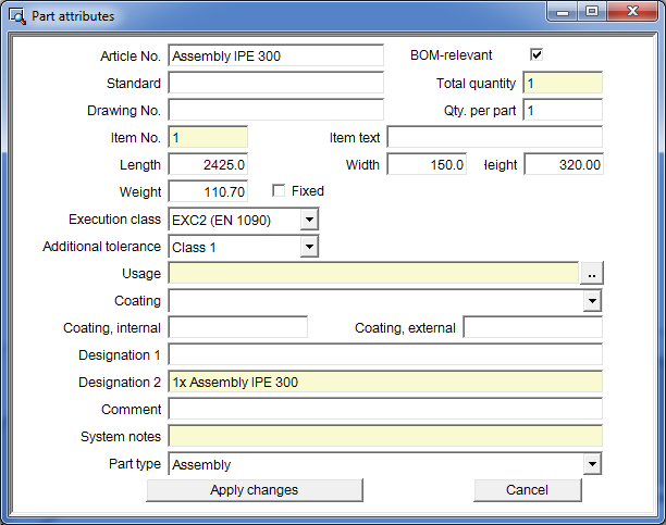
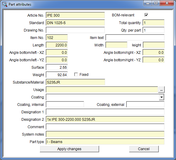
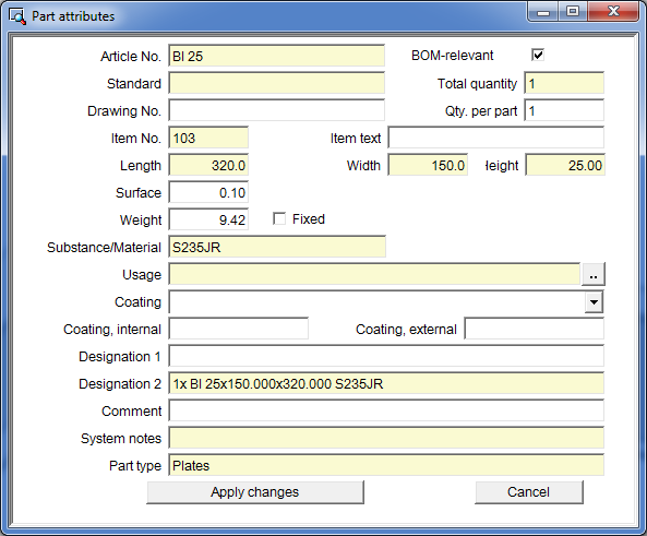
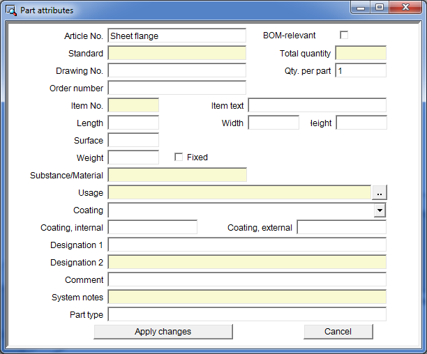
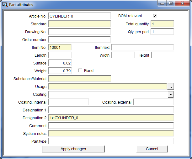
If you have selected the ISD default template for Steel/Metal Engineering for the parameter configuration (s.a.), the Part attributes masks in the HiDAD sys directory will be replaced accordingly. These masks have been slightly modified in SP2. For example, these masks now contain the fields Article No.and Standard instead of the fields "Part name" and "Article number". Also, the position of some fields has changed.

![]()
Previously, various Steel Engineering settings could be specified in the system file STB_PARAMETER.DAT which is now no longer available. Its setting options have been moved to the Configuration Editor at Steel Engineering.
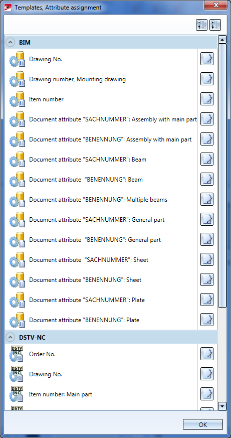
Use the new Templates, Attribute assignment  function to adjust the templates for attribute assignment
|
Standard templates for BIM |
Settings for |
|
BIM_PDM_DrawingnumberGeneration.ftd |
Generation of individual drawing numbers The number will be assigned to the HELiOS attribute Drawingnumber_text. |
|
BIM_PDM_ItemnumberGeneration.ftd |
Generation of individual item numbers The number will be assigned to the HELiOS attribute Component_itemnr_text. |
|
BIM_PDM_MountingDrawingnumberGeneration.ftd |
Generation of individual drawing numbers for mounting drawings The number will be assigned to the HELiOS attribute Drawingnumber_text. |
|
BIM_PDM_WSD_Assembly_ArticleNumber.ftd |
Configuration of the HELiOS document attribute SACHNUMMER for detail drawings of assemblies(assemblies with a main part) |
|
BIM_PDM_WSD_Assembly_Designation.ftd |
Configuration of the HELiOS document attribute BENENNUNG for detail drawings of assemblies(assemblies with a main part) |
|
BIM_PDM_WSD_Beam_ArticleNumber.ftd |
Configuration of the HELiOS document attribute SACHNUMMER for detail drawings of beams |
|
BIM_PDM_WSD_Beam_Designation.ftd |
Configuration of the HELiOS document attribute BENENNUNG for detail drawings of beams |
|
BIM_PDM_WSD_Multi_Designation.ftd |
Configuration of the HELiOS document attribute BENENNUNG for detail drawings of multi-part beams |
|
BIM_PDM_WSD_Part_ArticleNumber.ftd |
Configuration of the HELiOS document attribute SACHNUMMER for detail drawings of general parts |
|
BIM_PDM_WSD_Part_Designation.ftd |
Configuration of the HELiOS document attribute BENENNUNG for detail drawings of general parts |
|
BIM_PDM_WSD_SheetMetal_ArticleNumber.ftd |
Configuration of the HELiOS document attribute SACHNUMMER for detail drawings of Sheet Metal parts |
|
BIM_PDM_WSD_SheetMetal_Designation.ftd |
Configuration of the HELiOS document attribute BENENNUNG for detail drawings of Sheet Metal parts |
|
BIM_PDM_WSD_SteelPlate_ArticleNumber.ftd |
Configuration of the HELiOS document attribute SACHNUMMER for detail drawings of Steel Engineering plates |
|
BIM_PDM_WSD_SteelPlate_Designation.ftd |
Configuration of the HELiOS document attribute BENENNUNG for detail drawings of Steel Engineering plates |
|
Standard templates for DSTV-NC |
Settings for the composition of |
|
DSTV_NC_Ordernumbertext .FTD |
Order number |
|
DSTV_NC_Drawingnumbertext .FTd |
Drawing number |
|
DSTV_NC_H_Itemnumbertext .FTd |
Item number: Main part |
|
DSTV_NC_H_Partnumbertext .FTd |
Part number: Main part |
|
DSTV_NC_Itemnumbertext .FTD |
Item number: Loose parts |
|
DSTV_NC_Partnumbertext .FTD |
Part number: Loose parts |
|
DSTV_NC_W_Itemnumbertext .FTD |
Item number: Attached part |
|
DSTV_NC_W_Partnumbertext .FTD |
Part number: Attached part |
|
DSTV_NC_Signaturetext .FTD |
Lettering |
|
DSTV_NC_Filename .FTD |
File name - NC |
 Please note:
![]()
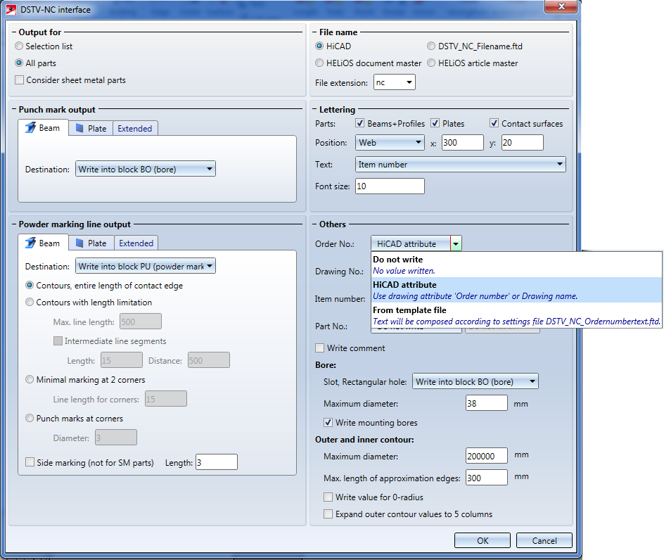
When generating DSTV-NC files the following data:
can be configured via template files (FTD) that have been defined for this purpose. Previously the selection took place via the Configuration Editor. From HiCAD 2016 SP2 onwards this can be done directly in the DSTV-NC interface dialogue window.
The DSTV templates will only be considered if the From template file option has been for the letterings, the order number, drawing number, item number and part number in the DSTV-NC interface dialogue window.
Use the Templates, Attribute assignment function to adjust the template files.
![]()
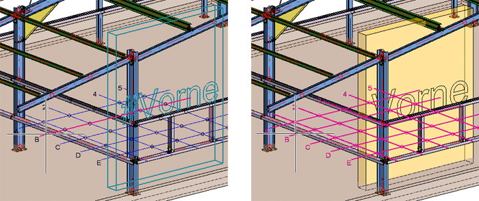
If there are several beams in succession that are aligned in the same direction, the railing elements of these beams will be combined into one segment assembly. As a result, continuous hand rails and knee rails will be formed on these beams.
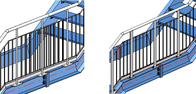
Left: Before HiCAD 2016 SP2; HiCAD 2016 SP2 or higher
![]()
If you selected the automatic calculation, the calculated width will be displayed in the (then greyed out) input field. Previously the value of the last manual width adjustment was shown here.
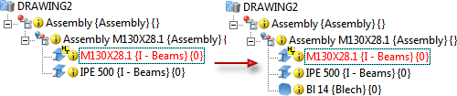
When you insert rectangular plates or stiffeners, HiCAD will now proceed as follows for the creation of welded assemblies:
If the reference beam is a main part that does not belong to an assembly, an assembly will be formed, with the beam as assembly main part and the plate as sub-part.
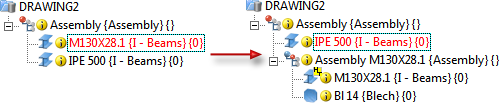
If the reference beam belongs to an assembly, the plate will also be assigned to this assembly as a sub-part.
![]()
If you use the All equal  button on the Stiffeners tab to apply the settings to all stiffeners in the Front plate connection (2330), please note that the placing of the stiffeners will be automatically mirrored in the process. For instance, if you have placed the 1st stiffener on the Front side, the 2nd stiffener will be placed on the Back side when you call theAll equal function.
For the
the Usage Filler plate is now automatically assigned to filler plates. In this way you can, e.g. also create usage-dependent configurations for filler plates, which will then be considered for drawing derivations.
![]()
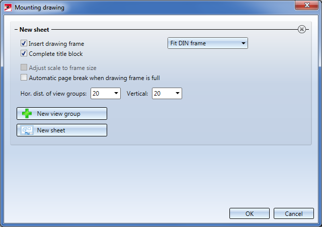
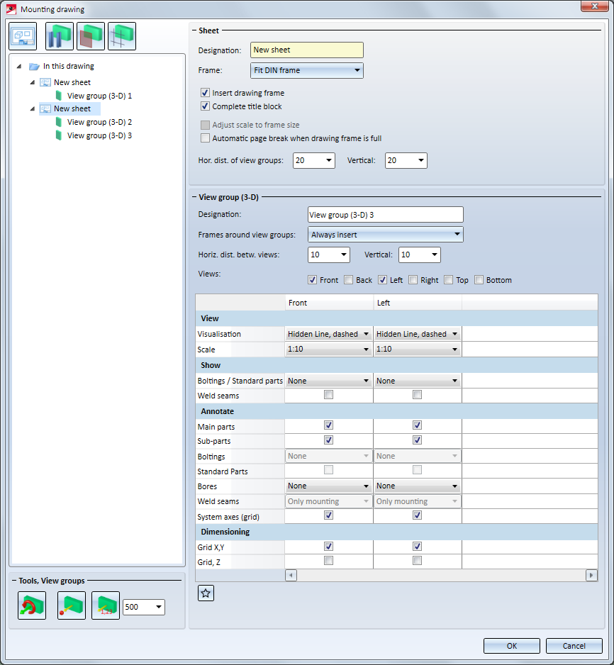
The dialogue window for the creation or modification of mounting drawings has been revised and enhanced. For example, the bounding boxes for view groups can now be changed subsequently, and mounting drawings can now also be output to external drawings.
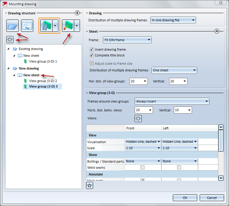
As of SP2, mounting drawings can also be output to external drawings. Please note that mounting drawings in external drawing files can only be updated after modifications in the original model drawing if you use document and drawing management in civil engineering (Management + BIM). In this case you will use the corresponding function in the Management+BIM module for the creation of the mounting drawings. In this way, the mounting drawing will be linked to the original model drawing.
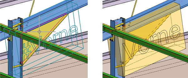
The dimensions of the transparent bounding box for the active view group can be changed via the functions of the

menu. The following functions are available:
 Change box dimensions, via facet + point
Here you select a surface of the box and move it to the desired target point. The moving can also be performed dynamically with the cursor.
 Change box dimensions, via facet + value
Here you select a surface of a box and determine the value by which the box is to be moved. The surface will be moved by the value that you enter in the input field.
Also new is the option to re-determine the box, namely, via the following functions:
 Re-determine box via 2 beams
 Re-determine box, via plane
 Re-determine box, via grid edge
The deleting of the box is now also possible - use the
 Delete box
function for this.
Clicking the  button opens the dialogue window shown below. Here you can determine the size of the boxes by specifying an excess length for different direction, i.e. enlarge the box in this way. Also, you can determine here how external drawings should be handled.
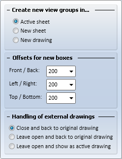
Via the parameter Include new parts in list views of mounting drawings you can specify whether created new parts are to be shown or hidden in the views of the mounting drawing upon its updating.
No
If a view of the mounting drawing contains hidden parts, the created new parts will also be hidden in these views.
Yes
Created new parts will always be shown in the views of the mounting drawing. This is the default setting. .

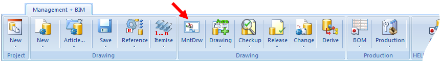
Like production drawings, mounting drawings can now be centrally managed with the functions of the Management + BIMmodule.
![]()
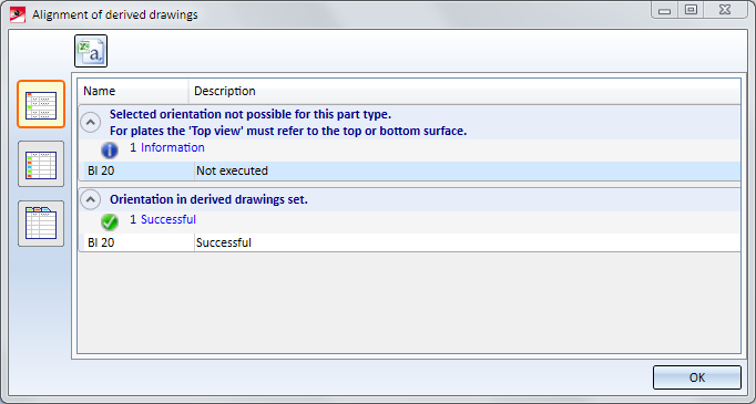
The Alignment of derived view functions in the context menu for parts (right-click)
 and
and 
can now also be applied to beams and profiles. In this way you can specify the alignment of views in workshop drawings.
When you specify the alignment, HiCAD will check whether the new alignment of the beam/profile is actually allowed. Please note the following:
The result of the check will then be shown in a dialogue window.Here it will be listed for which of the chosen beams/profiles the new alignment was successful, and to which no new alignment could be applied.
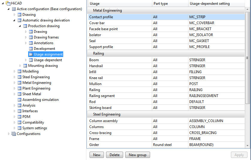
For each usage you can specify whether the boltings in the production drawing are to be shown or hidden. You can find the relevant settings in the Configuration Editor at
Automatic drawing derivation > Production drawing > Usage-dependent > name > Views
with name being the name of the respective usage.
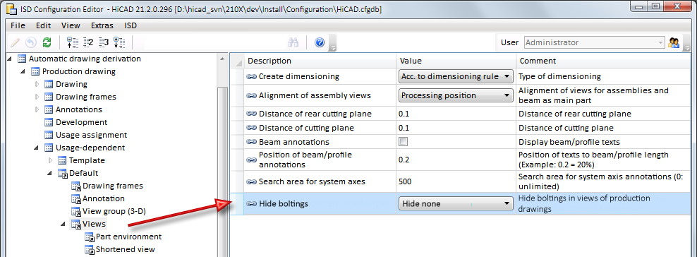
The following options are possible:
|
Hide none |
No bolts are hidden. This is the default setting and corresponds to the behaviour before HiCAD 2016 SP1. |
|
Hide all |
All bolts are hidden. |
|
Hide only "site bolts" |
Only bolts with the "Site assembly" or "On-site construction" property are hidden. |
Please note:
When generating the production drawing, a sectional view will now not only be created and dimensioned for attached parts of the type "Plate", but also for other, plate-like attached parts, such as flat steels.
Main parts that do not belong to an assembly, e.g. parts on the highest level of a part structure, were previously treated as main part of an assembly when a production drawing was created. This means: If the Main parts as assembly checkbox beneath View groups to be created for: in the Drawing derivation dialogue window was activated, the settings for assemblies were used for these parts. If the Main parts, individually checkbox was activated, the settings for the corresponding part type were used for these parts. If both checkboxes were activated, two drawings (view groups) were created - one for the assembly and one for the individual part.
As of SP2 these parts will only be considered for the production drawing if the Main parts, individually checkbox beneath View groups to be created for: in the Drawing derivation dialogue window was activated. In this way it is assured that only one view group will be created for such a part.
Parametric dimensions for Sheet Metal parts
You can now also use parametric Sheet Metal dimensions for the automatic dimensioning of Sheet Metal parts in workshop drawings. The following rule are available for this purpose:
| Rule | Internal designation | |
|---|---|---|
|
132 |
Sheet length |
SHEETMETAL_LENGTH |
|
133 |
Sheet width |
SHEETMETAL_WIDTH |
|
134 |
Sheet height |
SHEETMETAL_HEIGHT |
|
135 |
Parametric linear dimensions of Sheet Metal parts |
SHEETMETAL_PARA_DISTANCE |
|
136 |
Parametric angular dimensions of Sheet Metal parts |
SHEETMETAL_PARA_ANGLE |
|
137 |
Parametric circlr dimensions of Sheet Metal parts |
SHEETMETAL_PARA_CIRCLEDIM |
Please note that for Rule 136 angles with 90, 180, 270 and 360 degrees will never be shown.
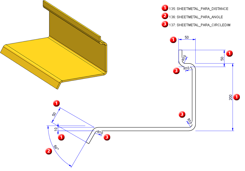
Example- 3-D sheet and detail of production drawing (front view) with dimensioning according to Rules 135, 136 and 137
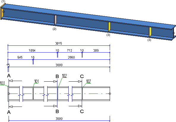
Expansion of rules for sub-systems
The following rules for sub-systems:
offer further selection options for reference selection:
Attached plates/sheets on relevant beam sub-parts
Sheets and plates in welded assemblies (welded frameworks) do not always refer to the main part of the assembly, but may also refer to the neighbouring beams (defined by contact surfaces). Such beams need not necessarily be main parts.
Based on the Rules 57 - 61, similar rules are now available for attached plates and sheets on relevant beam sub-parts.
|
105 |
Attached plates/sheets on relevant beam sub-parts; one dimension chain for each plate/sheet |
ATTACHING_SHEETS_SEPERATELY_RELVPROFS |
|
106 |
Attached plates/sheets on upper beam sides on relevant beam sub-parts; via bores or outer contour |
ATTACHING_SHEET_UPPERSIDE_RELVPROFS |
|
107 |
Attached plates/sheets on lower beam sides on relevant beam sub-parts; via bores or outer contour |
ATTACHING_SHEET_LOWERSIDE_RELVPROFS |
|
108 |
Attached plates/sheets on web surface on relevant beam sub-parts, before web, via bores or outer contour |
ATTACHING_SHEET_BEFORE_WEB_RELVPROFS |
|
109 |
Attached plates/sheets on web surface on relevant beam sub-parts, after web, via bores or outer contour |
ATTACHING_SHEET_BEHIND_WEB_RELVPROFS |
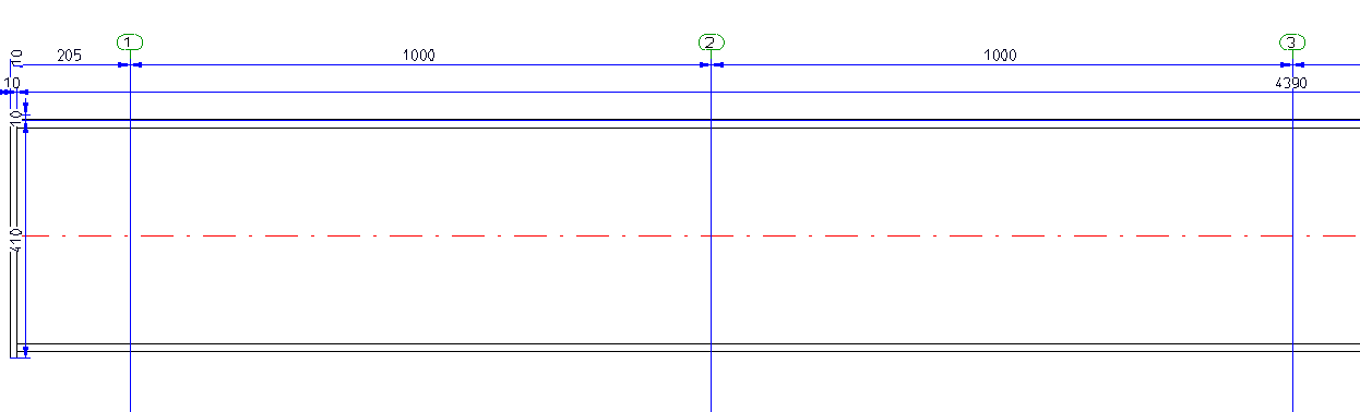
Separate chain dimensions for different usages
You have the option to create separate chain dimensions per different usage for chain dimensions describing the fitting situation of parts. To change this behaviour, open the STW_DimSettings.XML (conventional dimensioning settings) file in the HiCAD sys directory and set the parameter SEPERATEDSUBPARTPOSITION to 1:
</PARAM><PARAM Name="SEPERATEDSUBPARTPOSITION" Typ="INT" Value="1">
The image below shows a beam with 4 plates for different usages (1=Front plate, 2=Reinforcement plate, (3) Stiffener) and the front view of the production drawing.
When dimensioning attached sheet/plate parts or plates and beams that border on dimensionally relevant beams, both contact points will always be dimensioned. If only the first contact point in the chain is to be dimensioned, open the STW_DimSettings.XML (conventional dimensioning settings) file in the HiCAD sys directory and set the parameter
</PARAM><PARAM Name="SUBPARTPOSITION" Typ="INT" Value="0">
to 1.
This setting affects the Dimensioning rules 8, 10, 66, 67, 68, 69, 70, 94,96, 110, 113, 114, 115, 116, 117.
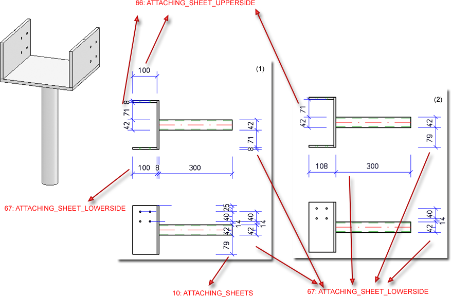
Example - (1) without changing STW_DimSettings.XML ; (2) with change of STW_DimSettings.XML
![]()
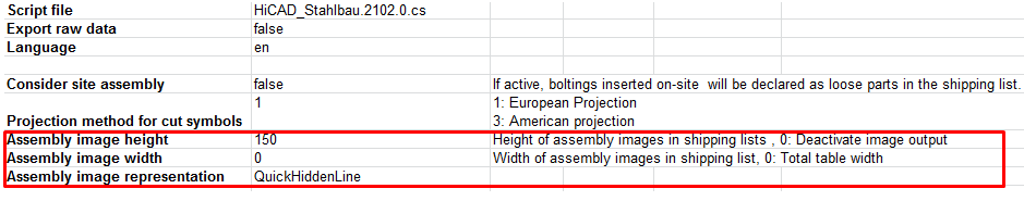
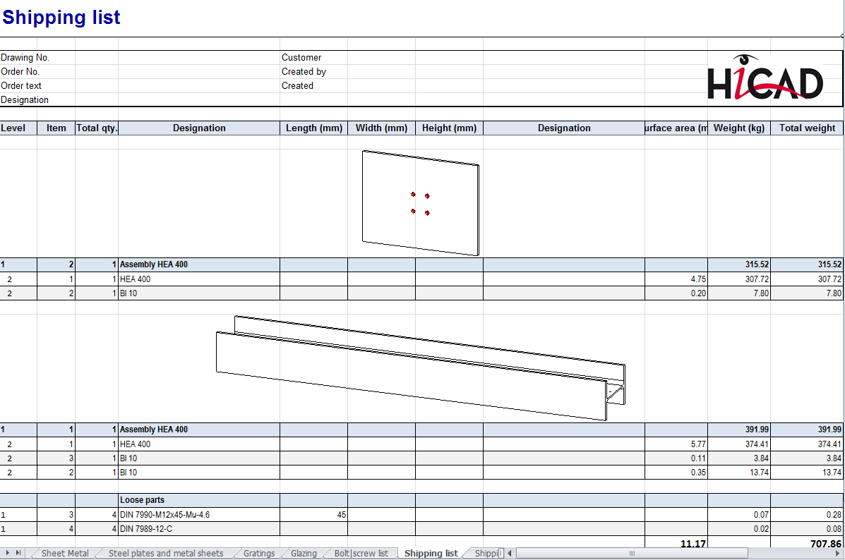
When generating BOMs using the HiCAD_Stahlbau.RMS template you can display an axonometric representation of the assembly as an image in the Shipping list in Excel format.
For this to happen, the following settings are required in the Excel file HiCAD_Stahlbau.EN.2102.0.xlsx:
|
Assembly image height |
Height of the image in pixels If you enter 0, image output will be deactivated.
|
|
Assembly image width |
Width of the image in pixels If the value 0 has been entered, the output of the image will be determined by the table width |
|
Assembly image representation |
Here you can specify the representation type of the image. Possible options are:
|
For image creation HiCAD must be running during Excel output via the Report Manager, and the corresponding drawing must be open.If a different drawing is open, to image will be created.
More information can be found in the News for the Report Manager.
![]()
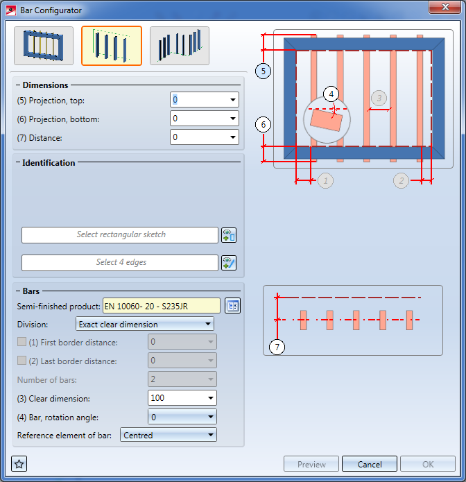
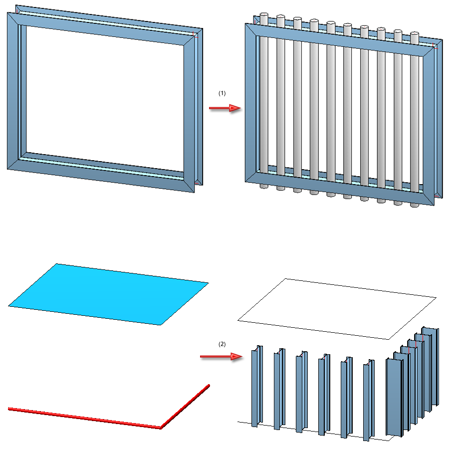
Use the Bar Configurator dialogue window to fill the area between 4 boundary beams, or the area between 4 edges of a sketch with bars. The placing of bars along composite edges is also possible.
![]()
The dialogue window for the creation and processing of mounting drawings has had a redesign:
The following new option for the specification of bounding boxes for detail views are available:
|
|
New view group by selection of 2 beams Here the bounding box is determined by the selction of 2 beam ends. HiCAD automatically calculates the smallest possible cuboid that completely covers the two beams, as visualized it as a transparent box in the drawing.
View group 1: Beam (1) and (2); View group 2: Beam (3) and (4) |
|
|
New view group by plane selection The bounding box is determined by the selection or definition of a processing plane. For the selection or definition of the processing plane you can use the same options as for the Processing plane function. The bounding box is created by extrusion of the processing surface to the front and to the back.
|
|
|
New view group by grid edge selection The bounding box is created by the selection of a Steel Engineering grid edge. lThe bounding box is created by extrusion of the edge running perpendicular to the grid edge to the front and to the back.
|
The transparent box that visualizes the bounding box can be changed via the functions beneath Tools, View groups. The bounding box can also be rotated.
Also new is the option to auto-create grid annotation tags for multi-level grids and add chain dimensions.
![]()
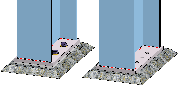
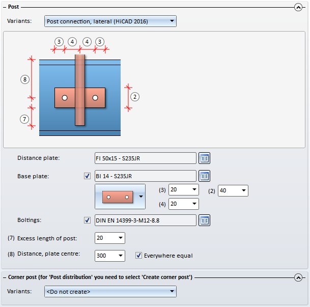
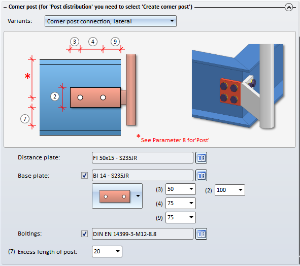
The lateral post connection has been optimized. You can now also choose between 2 bores or 4 bores in fixing plates.
When inserting corner posts, you can now specify on the Corner post - Substructure tab how the post is to be mounted to the substructure.
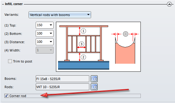
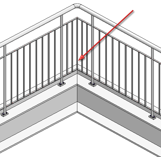
For vertical rods you have the additional options to place one rod in the corner. To do this, activate the Corner rod checkbox on the Infill tab.
The functions
can also be applied to stairs and railings that were created with the Staircase/Railing Generator if you have subsequently deleted parts that were created by the corresponding variant. However, these deleted parts will be re-created upon updating if these are required due to the parameters and the geometrical situation.
![]()
Steel Engineering boltings now also include the new bolt types
![]()
Previously, assembly points could be snapped during selection of beams and profile, causing the confusing error messagePart is no Steel Engineering part. From HiCAD 2016 SP1 onwards, only actual beam and profile-related data will allow the selection of beams.
The handling of manually assigned article masters during exchanging of semi-finished products can be specified in the Configuration Editor at System settings > HELiOS.
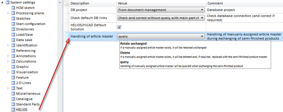
The following setting options for the parameter Handling of article master are available:
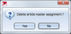
If you choose Yes, the article master of the semi-finished product to be exchanged will be deleted and, if required, replaced with the article master of the semi-finished product to be exchanged. If you choose No, the article master of the semi-finished product to be exchanged will be retained unchanged. This is the default setting.
At Taking over of semi-finished product attributes you can additionally specify which semi-finished attributes will be assigned to the manually assigned article attributes. The assignment must be defined as follows:
Semi-finished product attribute;Article attribute
Each assignment must be specified in a separate row in the collection, e.g. as follows:
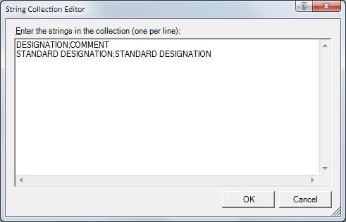
The String Collection Editor is initially empty by default.
![]()
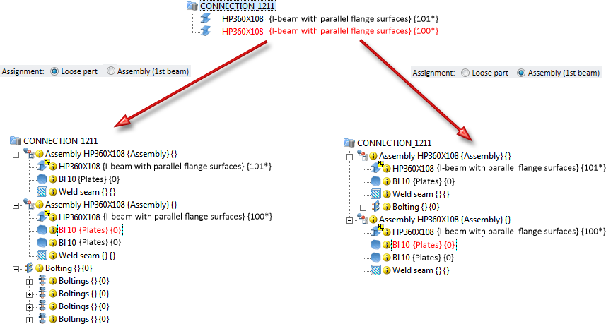
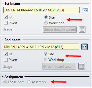
The assigning of bolting has been changed for the following connections:
1211
The bolting is inserted as a Bolting group. Next to Assignment on the Boltings tab you can specify whether this Bolting is to be assigned to the assembly of the 1st beam or whether it is to be inserted as a "Loose part". If you choose the "Loose part" option, the Bolting group will be inserted as a separate assembly on the same level as the assembly of the 1st beam.
2320
The bolting is inserted as a Bolting group. Next to Assignment on the Boltings tab you can choose whether this Bolting group and the reinforcement plates are to be assigned to the assembly of the 1st beam or are to be inserted as Loose parts. If you activate the Assembly (1st beam) option, the Bolting group and the reinforcement plates are assigned to the assembly of the 1st beam. If you activate the Loose partoption, the Bolting group will be inserted as a separate assembly on the same level as the assembly of the 1st beam. The reinforcement plates will be assigned to a structure assembly called Loose parts that also contains filler plates. This structure assembly is also located on the same level as the 1st beam.
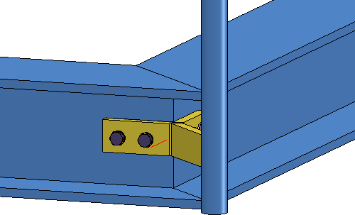
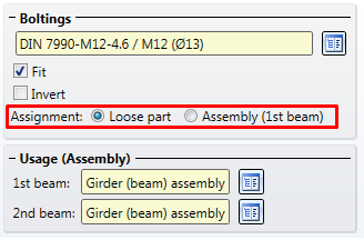
2330
The bolting is inserted as a Bolting group. Next to Assignment on the Boltings tab you can specify to which assembly the boltings and the reinforcement plates are to be assigned. If the Assembly 1st beam option is active, the boltings and the reinforcement plates will be assigned to the assembly of the 1st beam. If you activate the Loose partoption, the Bolting group will be inserted as a separate assembly on the same level as the assembly of the 1st beam. The reinforcement plates will be assigned to a structure assembly called Loose parts. If you have also inserted filler plates, reinforcement plates and filler plates will be located in this assembly.
Use this new function to connect two beams by means of two rigid front plates that are bolted together. These can either be flush or with excess length to the top, the bottom or the sides. The bolting can be aligned symmetrical or unsymmetrical. If required, the beams can be automatically shortened, lengthened or mitre cut. Furthermore, weld seams or filler plates can be directly inserted.
The connection can be made either to the web or to the flange. Allowed beam types are I-beams, U-beams, L-beams, T-beams, Z-profiles, pipes and hollow profiles.
The connection can either be user-defined or configured via predefined DAST tables integrated in HiCAD.
This connection replaces the previous Purlin joint 1201.
Use this function to connect an end plate to a beam. The plate can be inserted with a bolting, pre-drilled, with or without filler plates, and with or without base. If desired, weld seams can be directly inserted.
Possible beam types are I-beams, U-beams, L-beams, T-beams, Z-profiles, pipes and hollow profiles.
Allowed semi-finished products for the plate are simple Plates, Flat steels, FLUTZ profiles, A3 Steel bars by Frankstahl or C3 Stainless steel bars.
The Design Variant 2102 replaces the previous Design Variant End plate 1102.
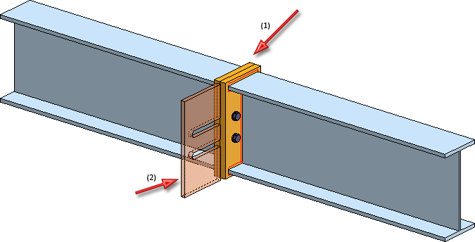
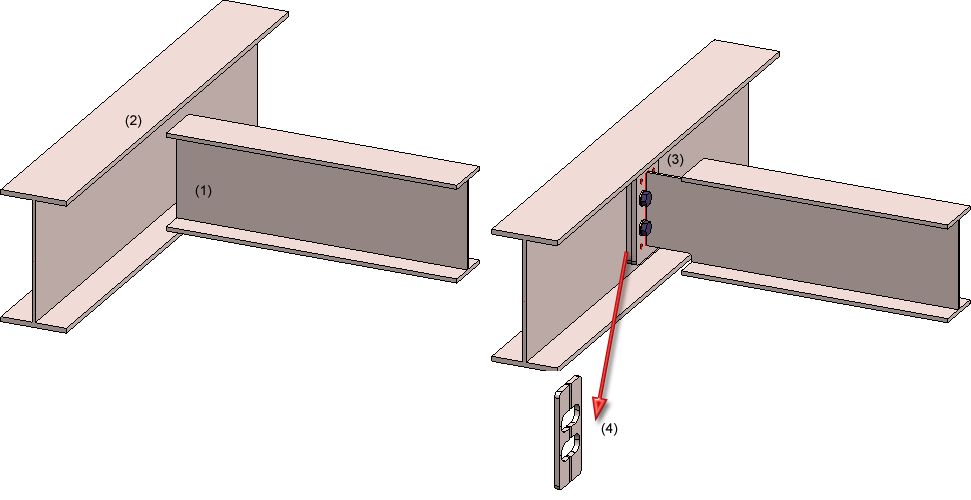
Use this function to connect two beams via front plate connections to a third beam. The connection can be made to the web or to the flange - with or without filler plates.
Depending on the fitting situation, the connected beam will be automatically notched appropriately. Furthermore, weld seams can also be directly inserted and annotated.
The connection can be a user-defined connection or configured via predefined DAST tables supplied with HiCAD.
Supported beam and profile types are I-beams, U-beams, T-beams, Z-profiles, pipes and hollow profiles.
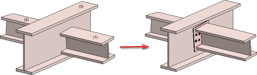
(1) 1st beam to be connected, (2) 2nd beam to be connected, (3) Target beam to which the connection is to be made
![]()
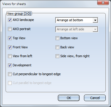
The following sectional views can now be selected for Sheet Metal parts in the Views for sheets dialogue window:
This sectional view is only created id a bend zone exists.
This sectional view is only created if a bend zone running perpendicular to the section path exists.
Bolts in workshop drawings can be hidden if desired. This is currently only possible via the Windows_Registry. To do this, select
HKEY_CURRENT_USER\Software\ISD Software und Systeme\HiCAD 2016
and create a new key:
|
Key |
Name |
WorkshopDrawing |
|
|
DWORD value
|
Name |
ModeScrewInvisibility |
|
|
Type |
DWORD |
||
|
Value
|
0 |
No bolts are hidden. This is the default setting and corresponds to the behaviour of HiCAD before Version 2016 SP1. |
|
|
1 |
All bolt are hidden. | ||
|
2 |
Only bolts with the property "Site assembly" or "Site production" are hiddden. | ||
|
<0 or >2 |
The default value 0 is used. |
||
 These settings do not apply to bolts and screws that are located in a structure assembly (e.g. to Boltings inserted as "Loose parts"). These bolts and screws are not shown in the workshop drawing.
The functions beneath Alignment of derived drawings in the context menu for parts:
and can now also be applied to Steel Engineering plates. This allows you to specify the alignment of plates in Workshop drawings. HiCAD will check whether the new alignment of the plate is actually allowed. The top view must be perpendicular to the upper or lower plate side!
The result of the check will then be shown in a dialogue window. Here it will be listed for which of the chosen plates the new alignment was successful, and to which no new alignment could be applied.
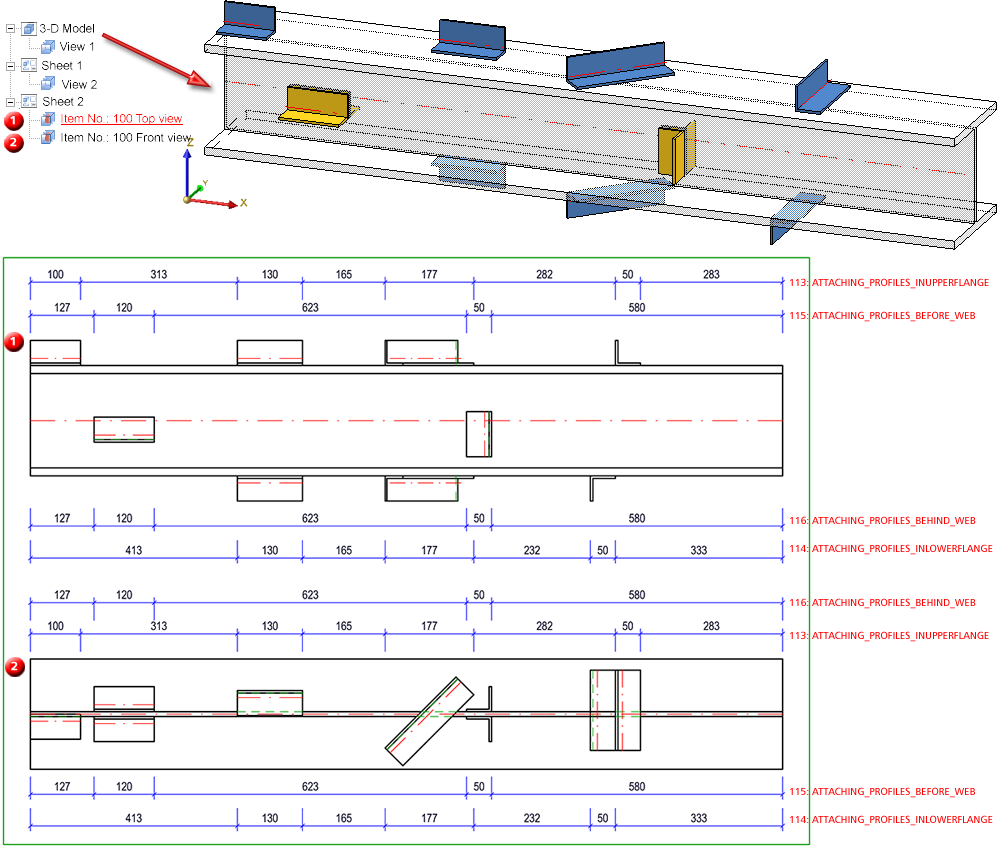
Separate dimensioning of beam sub-parts which are not vertical to main part axis
The following new rule allow a dimensioning of beam sub-parts that are not vertical to the main part axis.
| Rule | Internal designation | |
|---|---|---|
|
113 |
Beam sub-parts, not vertical to main part axis |
ATTACHING_PROFILES_INUPPERFLANGE |
|
114 |
Beam sub-parts on lower flange, not vertical to main part axis |
ATTACHING_PROFILES_INLOWERFLANGE |
|
115 |
Beam sub-parts in front of web, not vertical to main part axis |
ATTACHING_PROFILES_BEFORE_WEB |
|
116 |
Beam sub-parts behind web, not vertical to main part axis |
ATTACHING_PROFILES_BEHIND_WEB |
|
117 |
Beam sub-parts, not vertical to main part axis |
ATTACHING_PROFILES |
If you select the direction Parallel to beam axis you can, depending on the respective position, create a chain of dimensions for the beam sub-parts.
If you select the direction Vertical to beam axis, a separate chain of dimensions will be created - vertical to the main part axis - for each beam sub-part.
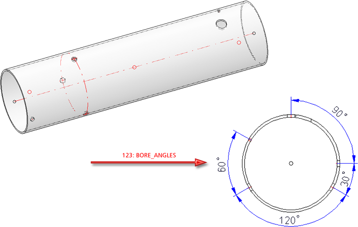
Dimensioning of bores with intersecting axes
Use the new dimensioning rule
123: Angle between bore axes (BORE_ANGLES)
to dimension bores with intersecting axes - this rule is of particular importance for machine-controlled drilling. This rule dimensions bores in beams and profiles with circular cross-sections (round steels, steel pipes), but only if the bore axes are running in the direction of the beam/profile axis.
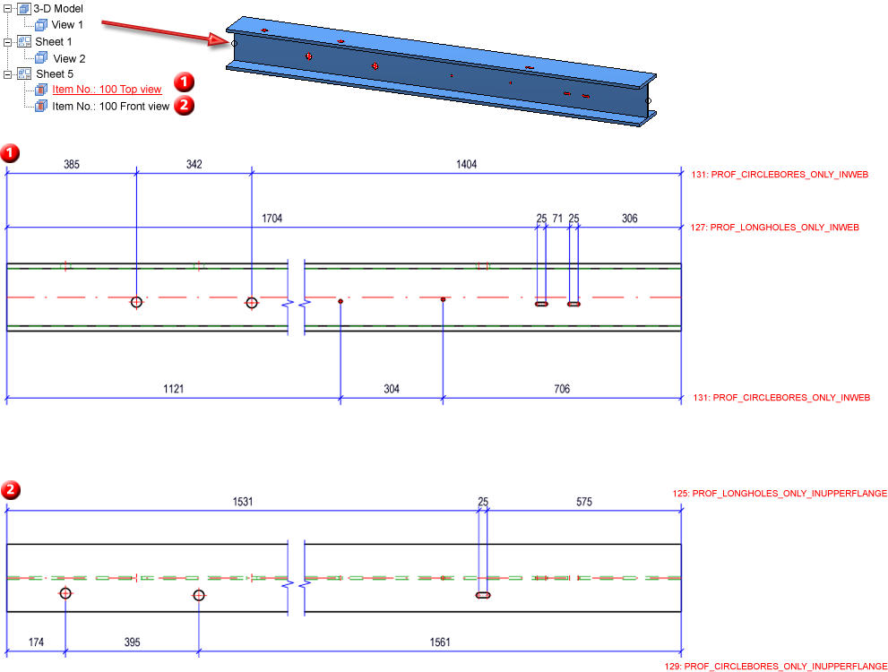
Dimensioning rules for various bore types
When creating production drawings, different dimensioning rules are now available for different bore types:
| Rule | Internal designation | |
|---|---|---|
|
124 |
Beam processings of the type Slot |
PROF_LONGHOLES_ONLY |
|
125 |
Beam processings of the type Slot in upper flange |
PROF_LONGHOLES_ONLY_INUPPERFLANGE |
|
126 |
Beam processings of the type Slot in lower flange |
PROF_LONGHOLES_ONLY_INLOWERFLANGE |
|
127 |
Beam processings of the type Slot in web |
PROF_LONGHOLES_ONLY_INWEB |
|
128 |
Beam processings of the type Circular bore |
PROF_CIRCLEBORES_ONLY |
|
129 |
Beam processings of the type Circular bore in upper flange |
PROF_CIRCLEBORES_ONLY_INUPPERFLANGE |
|
130 |
Beam processings of the type Circular bore in lower flange | PROF_CIRCLEBORES_ONLY_INLOWERFLANGE |
|
131 |
Beam processings of the type Circular bore in web | PROF_CIRCLEBORES_ONLY_INWEB |
Only bores with bore axis in viewing direction will be considered. For circular bores, a separate chain of dimensions will be created for each bore diameter;
Dimensioning rules for stairs
For staircases you can now use the following dimensioning rules:
| Regel | Interne Bezeichnung | ||
|---|---|---|---|
|
Total dimensions, axially parallel |
2 |
Assembly length |
ASSEMBLYLENGTH |
|
19 |
Assembly height |
ASSEMBLY_HEIGHT |
|
|
20 |
Assembly width |
ASSEMBLY_WIDTH |
|
|
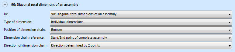
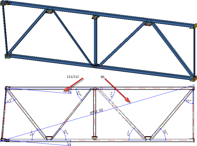
Transport dimensions |
90 |
Diagonal total dimensions of an assembly |
TOTAL_SIZE_ASSEMBLY |
|
Angles between stringers |
111 |
Angle between beam main part and connected sub-part beams |
ANGLE_CONNECTED_PROFILES(for the main part) |
|
112 |
Angle between relevant beams and connected sub-part beams |
ANGLE_CONNECTED_PROFILES_RELPROFS (for the relevant sub-parts) |
|
|
Sub-parts |
94 |
All attached parts of relevant beam sub-parts, via outer contour |
ATTACHING_PARTS_RELVPROFS |
|
96 |
Attached Sheet Metal parts with bores on relevant beam sub-parts |
ATTACHING_SHEETS_RELPROFS |
|
|
110 |
Beam sub-parts on relevant beam sub-parts |
ATTACHING_PROFILES_VERT_RELVPROFS (for the relevant sub-parts) |
|
|
Bores |
98 |
Bores in web of relevant beam sub-parts |
PROFBORES_INWEB_RELVPROFS |
|
99 |
Bores in upper flange of relevant beam sub-parts |
PROFBORES_INUPPERFLANGE_RELVPROFS |
|
|
100 |
Bores in lower flanges of relevant beam sub-parts |
PROFBORES_INLOWERFLANGE_RELVPROFS |
|
|
101 |
Bores in flanges of relevant beam sub-parts |
PROFBORES_INFLANGES_RELVPROFS |
|
![]()
The adding of 3-D parts to a Steel Engineering parts may cause problems with subsequently called functions, e.g. mitre cuts, Steel Engineering connections, NC/NCX export, deriving of drawings, etc. Attributes (e.g. weight, length, etc.) may also be calculated incorrectly.
In such cases, HiCAD will display the following warning message after selecting 3-D-Standard > Process > Add  function :
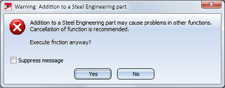
You can then decide whether you want to execute the function or not.
If you do no longer want this message to be displayed, activate the Suppress message checkbox. In this case, the adding will either be accepted or refused, depending on your last choice in the message window.
Please remember that the checkbox status applies only to the current HiCAD session!
![]()
Please note:
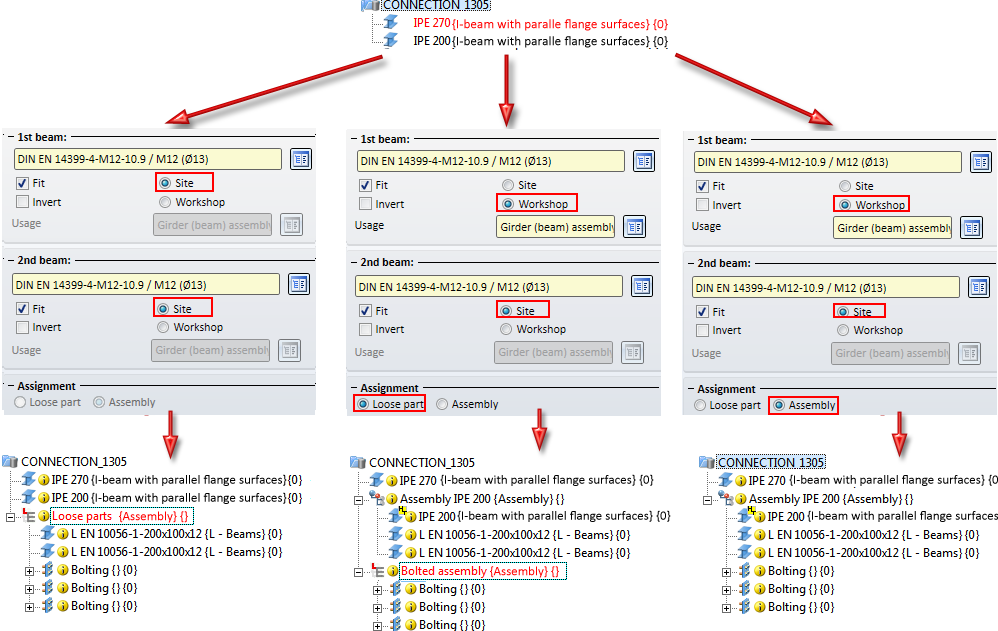
When creating boltings via Design Variants as accessory parts (Staircase/Railing Configurator) or loose parts (Connections 2320, 2322, 2330, 1305, 1306, 1211) in a non-BOM-relevant assembly, no DSTV BOM can be written, because the superordinate part is missing. This can be avoided for the mentioned connections by activating the Assignment: Assembly option on the Boltings tab of the corresponding dialogue window. Bolting structures created by the Staircase and Railing Configurator must currently be adjusted manually.
You can now create, modify and expand Steel Engineering Mounting drawings in only a few steps.
These mounting drawings have the following properties:
For the creation, changing and updating of mounting drawings the functions
 and
and
are now available at Drawing > Itemisation/Detailing.
Please note that the mounting planning functionality supplied with the Major Release HiCAD 2016 (V. 2100.0) is only a basic functionality, which will be continually enhanced in future versions.
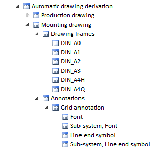
As with production drawings, you can specify various settings for mounting drawings in the Configuration Editor. You can find these settings at er Automatic drawing derivation > Mounting drawings:
The Part annotation templates function has been expanded for mounting drawings. There, you can now specify the representation of annotations for main parts, sub-parts, standard parts and boltings:
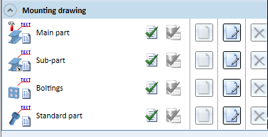
| Standard template files for mounting drawings | Annotation settings for |
|
PosNummer_MtZ_Hauptteil |
Main parts in assembly drawings |
|
PosNummer_MtZ_Nebenteil |
Sub-parts in mounting drawings
|
|
PosNummer_MtZ_Normteil |
Standard parts in mounting drawings
|
|
PosNummer_MtZ_Verschraubung |
Boltings in mounting drawings |
![]()
New front plate connections are available, replacing the previous connections 1320 and 1322 and providing significantly more flexibility during insertion.
Front plate connection to web/flange (2320)
Use this function to connect 2 beams via a bolted front plate connection. The connection can be made to the web or to the flange - with or without filler plates. Depending on the fitting situation, the connected beam will be automatically notched appropriately. Furthermore, weld seams can also be directly inserted and annotated.
The connection can be a user-defined connection or configured via predefined DAST tables supplied with HiCAD.
Supported beam and profile types are I-beams, U-beams, T-beams, Z-profiles, pipes and hollow profiles.
(1) Beam to be connected, (2) Target beam to which the connection is to be made, (3) Created connection, (4) With filler plates
Front plate connection to flange (2330)
Use this function to connect two beams via a bolted front plate connection. The connection can be made to the web or to the flange - with or without filler plates. In contrast to the connection 2320 the connected beam will not be automatically notched. Furthermore, you have the option to insert stiffeners between the flanges of the beam to which the connection is to be made.
The connection can be a user-defined connection or configured via predefined DAST tables supplied with HiCAD.
Supported beam and profile types are I-beams, U-beams, T-beams, Z-profiles, pipes and hollow profiles.
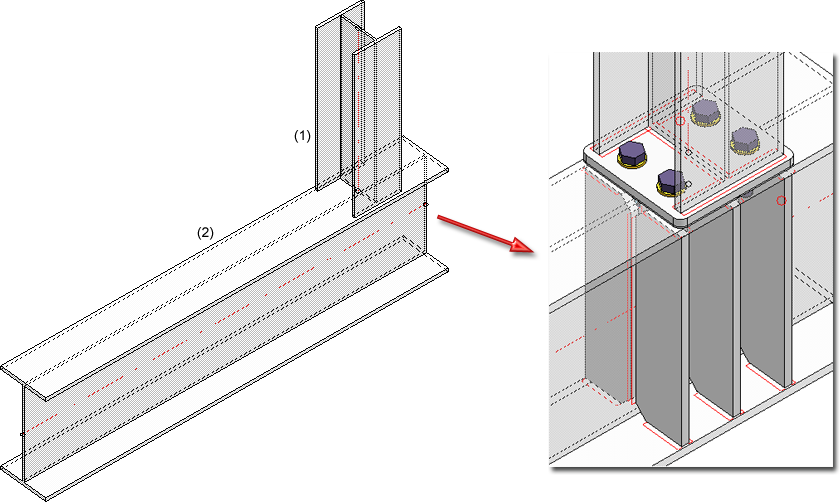
(1) (1) Beam to be connected, (2) Target beam to which the connection is to be made, (3) Created connection with stiffeners
Front plate connection to web, double-sided (2322)
Use this function to connect two beams via front plate connections to a third beam. The connection can be made to the web or to the flange - with or without filler plates.
Depending on the fitting situation, the connected beam will be automatically notched appropriately. Furthermore, weld seams can also be directly inserted and annotated.
The connection can be a user-defined connection or configured via predefined DAST tables supplied with HiCAD.
Supported beam and profile types are I-beams, U-beams, T-beams, Z-profiles, pipes and hollow profiles.
(1) 1st beam to be connected, (2) 2nd beam to be connected, (3) Target beam to which the connection is to be made
This function now offers the option to define whether the bolting is to be assigned to the assembly of the 1st beam or if it is to be inserted as a "loose part". The Bolting tab has been expanded for this purpose.
The assigning of boltings has changed here. The Bolting tab has been expanded for this purpose.
![]()
Previously, gratings were handled like plates with regard to the calculation of their weights and surface areas. It is now possible to specify the surface area per square metres of installation area for Gratings according to DIN 24537. For this purpose, the NETOBERFL column is available in the corresponding table of the Catalogue Editor.
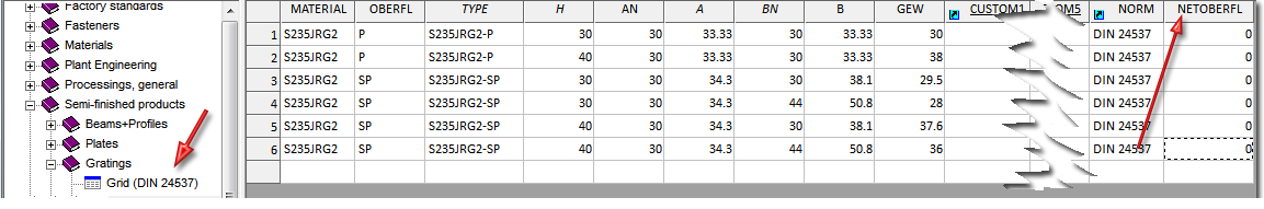
The default setting is the value 0. For the calculation of the net weight and the net surface area, enter the desired value here and save the table.
When inserting gratings, the value specified in the table will be considered for the calculation of the net surface area. In addition, subtractions and chamfers are also taken into account when weights and surface areas are calculated.
(1) Grating insertion with value 0, (2) Grating insertion with value 5.5, (3) Grating with chamfer
![]()
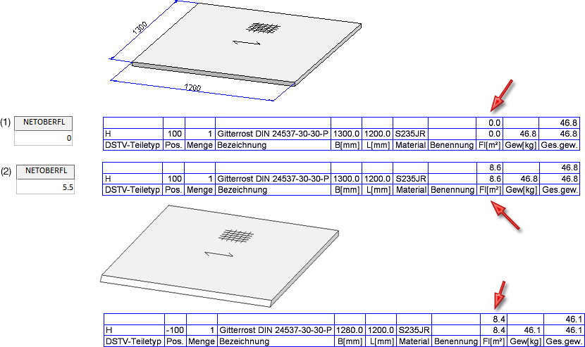
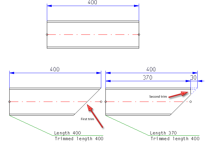
When beams are trimmed, the value assigned to the part attribute Length will be the total length of the trimmed beam. If two trimmings are applied to a beam, the calculated length will be the smaller of the two individual total lengths after applying the trimming. The beam length and the trimmed length will then be identical.
Line for 1st trimming; (2) Line for 2nd trimming
Exceptions are cases where one of the trimmings is performed at a 90° angle. In such cases, the length resulting from the 90° trimming will not be considered for the calculation of the minimum (the reason for this are processing steps with a saw). Use the part attribute
Trimmed length (§24)
for a correct calculation of the trimmed length. This attribute can, for instance, be used for annotations, in part attribute masks or in BOMs.
![]()
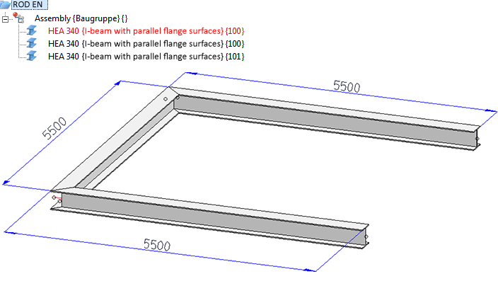
For bar optimisations ("bars"=bar-shaped symbolic representations of beams) you have now the option to shorten a particular number of bars by specifying the number of residual lengths. This can be done with waste minimisation or with a preference of residual pieces.
The specification of the bars and the number of residual pieces must be entered manually into the Excel template before creating the BOM.
For this purpose, the Bar settings sheet has been added in the HiCAD_Stahlbau.xlsx template for the output of BOMs to Excel.
An example:
The drawing shown below consists of three beams of the type HEA 340 and a length of 5500 each.
Profiles with a length of 6000 and 6500 are to be used. When using the length of 6500, however, not more than one residual piece is to be created. For this to happen, the default settings on the Bar settings sheet in the file HiCAD_Stahlbau.xlsx must be changed as follows:

The amount of waste is to be as small as possible; therefore, the Prefer residual lengths switch must remain on false.
If you generate the Excel file with this setting, three bars with a length of 6000 mm will be used. The amount of waste will be 1500 mm here.
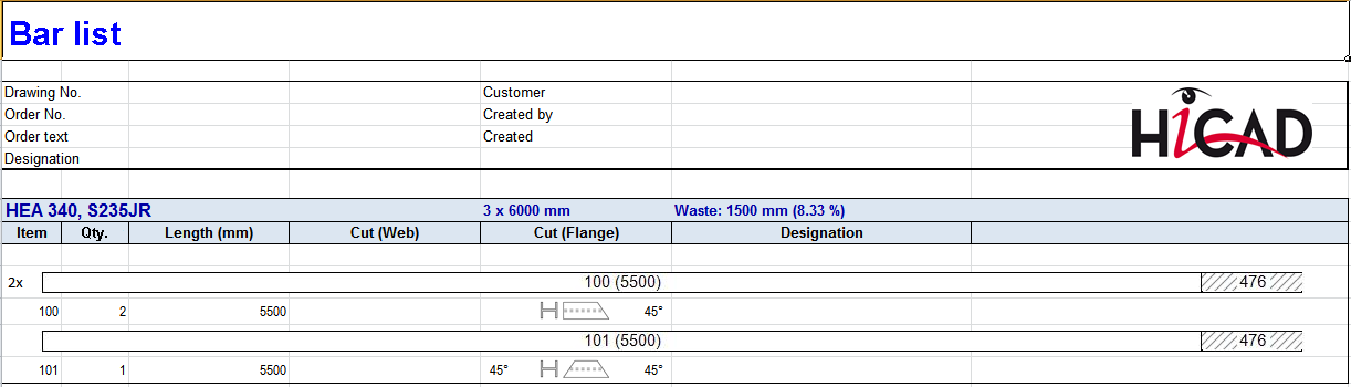
In contrast, if you set the Prefer residual lengths switch to true, two 6000 mm bars and one 6500 mm bar (because of Qty. = 1). Here, the amount of waste will be 2 x 1000 mm.
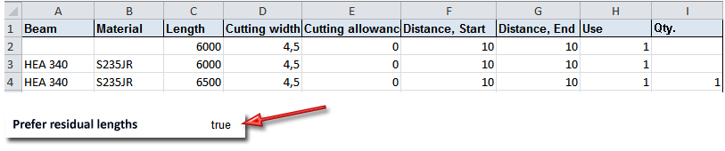
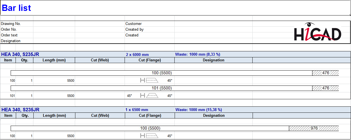
If the quantity of the 6500 mm bars was 2, one 6000 mm bar and two 6500 mm bars would be used etc.
Further information on the output of BOMs can be found here.
![]()
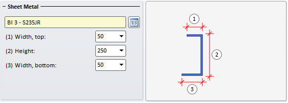
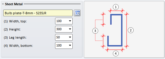
The Stringers tab of the Staircase Configurator has been changed. Here, you now have different dialogues for stringers made of Sheet Metal U and Sheet Metal C.
![]()
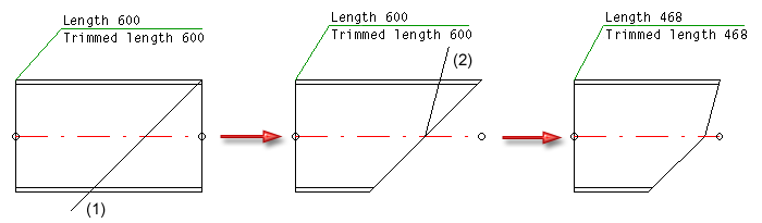
The Post - Substructure tab has been expanded.
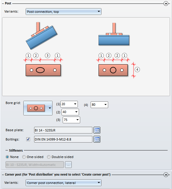
If you select the Post connection, top variant, you can choose a bore grid. You have now the following options:
![]()
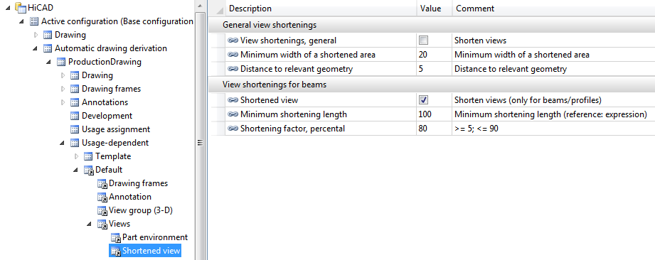
In the Configuration Editor, the assigning of usage-dependent settings has been simplified and enhanced.
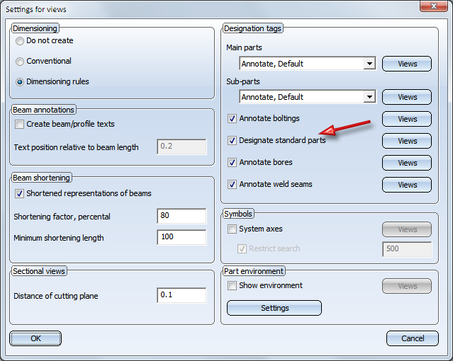
Previously, only views of beams and profiles could be shortened. This is now also possible for other views, e.g. views of Sheet Metal parts etc. For this purpose, the Settings for views dialogue window has been modified. There you can specify beneath Shortened view which views are to be shortened.
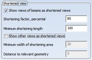
If you also want to shorten other views , e.g. views of the Sheet Metal parts, activate the Show other views as shortened views checkbox, enter the minimum width of the area to be removed by the shortening, and the distance of th shortening to the relevant geometry.
(1) Distance of shortening to relevant geometry
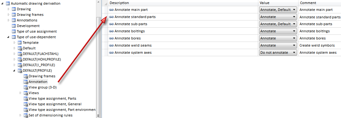
If the settings for drawing derivation are loaded from a configuration, the settings specified in the Configuration Editor at Automatic drawing derivation > Production drawing > Usage-dependent > name > Views > Shortened view will be evaluated. name denotes the name of the corresponding usage.
You can now also create sectional views for standard beams of the category Flat steel for derived drawings, if this was correspondingly specified at View groups.
In HiCAD 2015, standard parts were annotated if you explicitly activated the annotation of sub-parts or (as of SP1) the annotation of boltings. As of HiCAD 2016 the annotation of standard parts can be switched on or off, independent of other annotation types.
If the settings for drawing derivation are loaded from a configuration, the settings specified in the Configuration Editor at Automatic drawing derivation > Production drawing > Usage-dependent > name > Views > Shortened view will be evaluated. name denotes the name of the corresponding usage.
The following new dimensioning rules are available for workshop drawings:
Previously, sectional views were only created for Steel Engineering plates. This is now also possible for plate-like profiles. Therefore, the dimensioning rules for plates now also apply to plate-like profiles in sectional views.
A new listbox for frames and view groups offers the following selection options:
The default setting is Always insert. This presetting can be changed in the usage-dependent templates in the Configuration Editor at: Automatisc drawing derivation > Production drawing > Usage-dependent > ... > View groups > Frames around view groups.
If a drawing frame contains only one view group, it will be centred in the drawing frame. This behaviour, too, can be changed in the Configuration Editor, at Automatic drawing derivation > Production drawing > Drawing > Centre individual view group. If you deactivate the checkbox, individual view groups will be placed at the top left of the drawing frame instead.
Colour, layer and line type of the frames can be specified in the Configuration Editor at System settings > Visualisation > View group.
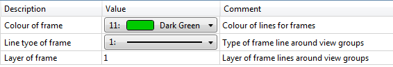
If the centring leads to collisions with locked areas (e.g. the title block), the view group will be placed at the top left.
![]()
Related Topics
|
Version 2102 - HiCAD Steel Engineering | Date: 15/11/2016 | © Copyright 1994-2016, ISD Software und Systeme GmbH |
 and
and