"Civil Engineering functions" docking window > Steel Engineering > Connections > Individual beam/profile > End plate (1102)
Use this function to fit end plates with pre-drilled bores, either with or without projection. Besides standard bores you can also use slots and free bores. The plate can either consist of sheet metal or flat steel. Furthermore, weld seams can be directly inserted if desired.

Configurations for end plates can be saved, enabling you to access your individual, customised configurations at any time.
You use the buttons on the left hand side of the dialogue window to configure the end plate.
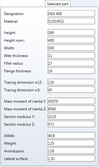
Selected part
This tab provides information on the previously identified beam, such as designation, material or dimensions etc. These entries cannot be changed.
Front plate
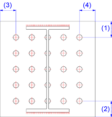
In this area you define the type and the size of the plate, its position on the beam, the bore type and the bore grid.
|
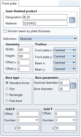
Semi-finished product The plate can consist of sheet metal or of flat steel. Click the If you want to shorten the beam to which you want to attach the plate by the plate thickness, activate the corresponding checkbox. |
|
Geometry / Position Three methods for geometry determination (plate size) are available. You can select tzhem from the Definition listbox:
Furthermore, you have the following options for the positioning of the plate: Plate x / Plate y You can position the plate, through specification of the corresponding settings, in such a way that particular points on the plate or a bore lie exactly in the centroid of the beam cross-section. Beam x / Beam y The plate will be positioned in such a way that the centroid of the beam cross-section lies in one of the displayed points of the beam. If you have specified an offset, the plate will be moved accordingly.
|
|
Bore type Here you can select the bore type. The following options are available:
|
|
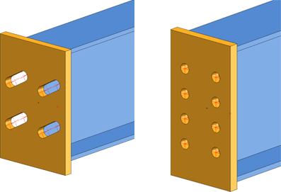
Bore grid The bore grid determines the position and arrangement of the bores on the end plate..
|
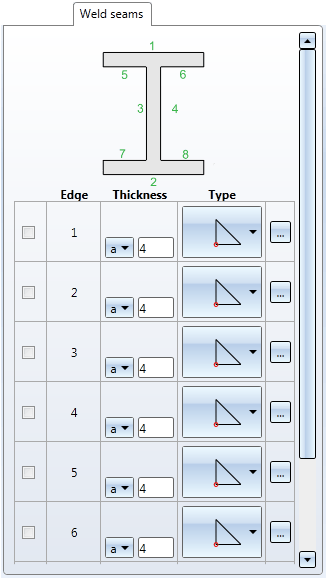
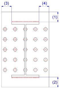
Weld seams
If you want to insert weld seams at the beam edges, select the required edges by activating the corresponding checkboxes.
You can specify the type and thickness of the weld seam for each edge. If desired, you can also add weld seam annotations: Click the  icon to open the Symbolic representation of weld seams dialogue. The dialogue is operated in the same way as the one for the Insert weld seam symbol 3-D function.
When all required data have been entered, you can fit the plate. If you select Apply, the plate will be fitted, but the dialogue window will remain open (in contrast to the OK option). If you exit the dialogue window with Close, the function will be cancelled, without fitting or changing the plate.
![]() Please note:
Please note:
![]()
Related Topics
Connections + Variants (3-D SE) • Dialogue Window for Connections - Type I (3-D SE) • The Catalogue System for Connections + Variants (3-D SE)
Version 1702 - HiCAD Steel Engineering | Date: 9/2012 | © Copyright 2012, ISD Software und Systeme GmbH
 The
The 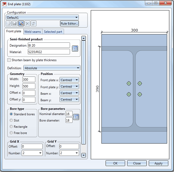
 icon to select plate type and material directly from the corresponding Standard part catalogues.
 symbol and then click the symbol. All fields will automatically be assigned the entered value