Drawing > Itemisation/Detailing > Drawing derivation
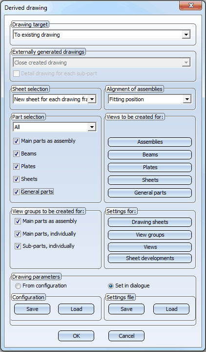
You specify the settings for derived drawings in the Derived drawing dialogue window:
The dialogue window consists of the following areas:

![]()
Derived drawings are created as sheet views of the current or new model drawing and can be called via the Views tab of the ICN at any time. The following targets for derived drawing creation are possible:
|
To existing drawing |
The derived drawing is created as sheet view of the current model drawing. |
|
To external drawing |
A new drawing file is created for the derived drawing. This drawing is saved to the same directory in which the original model drawing is located. The file name is composed of the prefix CD and an unambiguous ID generated by HiCAD, e.g. CD_263485165. The workshop drawing is assigned to the sheet with the number n . |
|
Detail drawings to external drawings |
An individual detail drawing is created for each of the itemised Steel Engineering parts in the current model drawing. |
|
New external drawing for each drawing frame |
A new drawing will be created for each drawing frame. The drawings will automatically be svaed to the same directory in which the original model drawing is located. The file name is composed of the prefix CD and a unique ID generated by HiCAD. |
If you have selected an external drawing as drawing target, the Externally generated drawings input area will be activated:
Detail drawing for each sub-part
If this checkbox is activated, a detail drawing will be created for each sub-part. This also applies to Steel Engineering parts which are sub-parts to a non-Steel Engineering part.
 If you use an external drawing as drawing target, and load the drawing parameters from a predefined configurations, parts appearing exclusively as "attached parts" in the workshop drawing will not be included in the drawing BOMs. You can change this behaviour in the Configuration Editor: Select GENERAL > DRAWINGS >CREATION > REMOVE BOM-RELEVANCE IN EXTERNAL DRAWING FROM NON-DETAILED PARTS. Deactivate the BOM-relevance for these parts in the workshop drawing (1=yes).
![]()
Derived drawings are created as sheet views of the current drawing or a new drawing and can be called at any time via the Views tab of the ICN. The following sheet settings are possible:
|
New sheet for each drawing frame |
A new sheet view is created for each drawing frame. |
|
New sheet for each assembly |
A new sheet view is created for each assembly. |
|
New sheet |
A new sheet view is created. |
|
Sheet n |
The derived drawing is assigned to the sheet with the number n. |
![]()
Assemblies can be aligned in the drawing in
This enables you to create drawings both for overview and processing purposes.
![]()
Here you specify which parts of the drawing are to be taken over in the workshop drawing.
|
All |
All parts are taken over into the workshop drawing. |
|
Only new |
Only new parts which are not yet in the workshop drawing are taken over. |
|
Select, individually |
The parts for the workshop drawing are specified individually by identification. When you exit the dialogue window, HiCAD prompts you to identify the required parts. Press the middle mouse button to end the selection. |
|
Selection list |
All elements of the active selection list are taken over. To create a selection list, press and hold down the CTRL key and identify the steel engineering parts you want to take over to the workshop drawing - either in the ICN or in the drawing. You can also select the parts by drawing a rectangle: Press and hold down the CTRL key and use the left mouse button to draw a rectangle around the required drawing detail. |
|
Assemblies Beams Plates Sheets General parts |
You can restrict the number of parts you want to take over to the workshop drawing by activating or deactivating the corresponding checkboxes. In this way you can, for example, auto-generate production drawings for sheet metal parts or general mechanical engineering parts. Please note the following:
|
![]()
![]()
Related Topics
Derived Drawing - Functions • Derive Drawings • Derived Drawings: Change Settings • Derived Drawings - Settings File or Configuration
Version 1702 - HiCAD Steel Engineering | Date: 9/2012 | © Copyright 2012, ISD Software und Systeme GmbH
 The
The