P+ID > Settings > Settings > Symbol
The Symbol tab is composed of the following sections:
In this section, you can select the required identification option.
If you select the Acc. to KKS (KraftwerksKennzeichnungsSystem = German for "Power Plant Designation System") button, identification is normally based on the plant name, plant details and parts; Identifications according to DIN are comprised of names. You can specify the composition in the Ident tab.
In this area, you can specify the properties of the KKS boxes. Text boxes are rectangular boxes positioned next to the symbol in flowcharts and are written into the symbol ID.
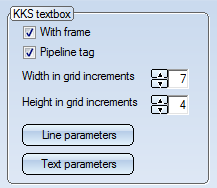
The following parameters can be preset:
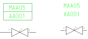
KKS text with and without frame
The pipeline tag which is normally used for pipeline symbols according to KKS can be switched off if desired. To do this, deactivate the Pipeline tag checkbox on the Symbol tab.
If this option is deactivated, pipeline symbols and pipeline information will be graphically represented in the same way as with the identification according to DIN.To retain the desired pipeline annotation, you need to adjust the symbols _PIPE0 and _PIPE2 (in the symbol library ISDDINSYM1_...) beforehand.
The nominal diameter can be shown in the appropriate entry and text fields in the dialogue box in mm and/or inches according to the given setting.
Nominal diameter specification can, irrespective of preset values, be entered as mm, inches and mm or inches. Values expressed as inches are indicated by the " character. Inch values are only accepted if they are contained in the assignment lists managed by HiCAD. These lists are stored in the \EXE\ANINCHTABKLE.DAT file. If necessary you can expand a list by a maximum of 50 lines containing additional nominal diameter assignments. It is also possible to insert new lines between existing ones.
Internally HiCAD works with nominal diameters in mm. The value output for a nominal diameter is based on the mm with respect to the given setting and the assignment table.
You can specify the width of the symbol in grid increments. The increment width for flowcharts is 2.5 mm. The width, based on the type of identifier (DIN or KKS), is automatically set.
This function enables you to determine line parameter values for the symbol. If possible, the preset Layer No. 3 should be retained.
Activate this option to allow deviation from the given nominal diameter of a pipeline.
An optional value can then be set for the nominal diameter of the pipeline symbol and the pipe part symbol respectively. The edited nominal diameter of the pipeline symbol is:
Please remember, when you select this setting automatic checks on nominal diameter values in the pipeline are not carried out, and you need to check values yourself.
If the nominal diameters of reductions are edited, values for nominal diameters in a symbol are only changed appropriately for parts without assignments.
The check is performed if the Check symbol identification for uniqueness has been activated in the P+ID settings.
The check is performed if the Check symbol identification for uniqueness checkbox has been activated in the P+ID settings.
The identifications of two symbols are identical (and therefore not unique) if their entries match for the following dialogue types (the dialogue code is set in brackets):
For identification according to DIN:
For identification according to KKS:
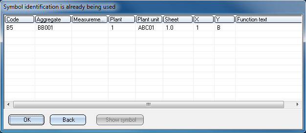
If a non-unique identification is entered, the symbols that already have this identification will be listed in a dialogue box.
If you mark a row with a left-click and select Show symbol, the symbol and its environment will be shown in a viewer window.
Select Back to get back to the input dialogue.
Select OK to apply the identification although it has been recognized as “non-unique”.
This new feature is only important if you use the HELiOS database for part data management.
The Ignore industry pre-setting during part search option is set if you choose the default settings. It influences the part search process when assigning parts to symbols via the Edit symbol function:
The table below explains in what ways part search can be influenced:
|
Requirements |
Effect |
||
|---|---|---|---|
|
|
Search for part only in part class specified by the part type ID, in the industry class specified by the industry ID. |
Search for part in the part class(es) specified by the part type ID, in the complete class structure. |
|
|
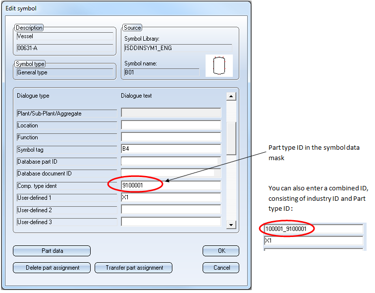
Combi-ID in symbol data mask |
yes |
no |
no |
|
HiCAD Plant Engineering module enabled |
yes/no |
yes |
yes/no |
|
Two-level part structure in database (two industries with corresponding part types on level below) |
yes |
yes |
yes/no |
|
Option Ignore industry presetting set |
yes/no |
no |
yes |
If you do not use the HiCAD Plant Engineering module, but the HiCAD P+ID module, the Ignore industry presetting during part search should always be set.
If you do not use the HiCAD Plant Engineering module in conjunction with the HiCAD P+ID module,the Ignore industry presetting during part search should not be set.
Related Topics
Version 1702 - HiCAD P+ID | Date: 9/2012 | © Copyright 2012, ISD Software und Systeme GmbH
 Example