Formerly the P+ID always occupied the HiCAD thumbnail with the highest number (i.e. number 18). Now, the P+ID can be processed in any thumbnail.
As a result, the directory structure of the processed file changes as follows:
..\PID\WORK\[Number of drawing thumbnail]\Name
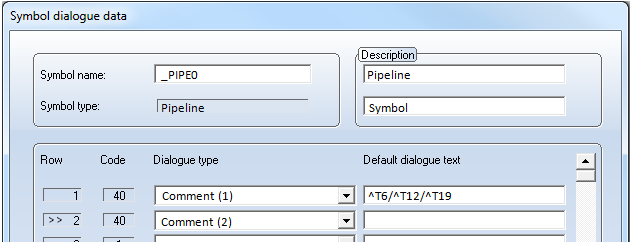
You can also use several placeholders in the form of ^Tn (n = Row number in database mask) in the Comment dialogue of a symbol data mask. You can place arbitrary texts before, between and after the placeholders. The text contained in the Comment dialogue can consist of a maximum of 255 characters after automatic replacement of the placeholder. The text replaced via a placeholder may also consist of a string for database attributes access.
The taking over of a database attribute value as dialogue text is also possible for pipeline symbols.
If you have assigned a pipe class to a pipeline symbol, you can use %DBPCLAT(name1) to access the value of a pipe class attribute. name1 stands for the name of a pipe class attribute , e.g. PRESSURE.
If you have also assigned a "Straight pipe" part to the pipeline symbol, you can use %DBAT(name2) to access the value of a part attribute of the straight pipe. name2 stands for the name of a part attribute, e.g. D_AUSSEN (D_OUTER for "Outer diameter").
![]()
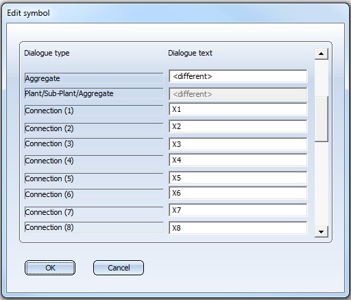
Use the new Edit several symbols function to change data mask contents for several symbols of a P+ID project at once. Proceed as follows:
A result list will be displayed.
The data of the symbols will be collected in the Edit symbol dialogue window. The <different> entries in the Dialogue text window indicates that the values for this dialogue type are different for the selected symbols.
For example, the following placeholders are supported:
^Tn for text replacement with row number n in the symbol data mask,
%DBAT(Attributname) for database attribute transfer,
%DBPCLAT (Attributname) for the pipe class attribute transfer.
The data will then be saved, and the graphic will be updated.
![]()
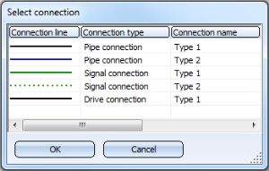
For both functions, a list of defined connection types will be displayed. Select the desired connection type with a double-click. Use the cross-hairs to specify the points. After creating a connection line, you can directly create another one with the same connection type without having to open the selection list once again.
If you select the functions Measuring point with circle and Measuring point without circle, the list of defined connection types will be displayed as well, but only containing the signal connections.
Owing to the new possibility to define an arbitrary number of connection types, the functions for the updating of connections have been adjusted accordingly.
The pipeline tag which is normally used for pipeline symbols according to KKS can be switched off if desired. To do this, deactivate the Pipeline tag checkbox on the Symbol tab.
If this option is deactivated, pipeline symbols and pipeline information will be graphically represented in the same way as with the identification according to DIN.To retain the desired pipeline annotation, you need to adjust the symbols _PIPE0 and _PIPE2 (in the symbol library ISDDINSYM1_...) beforehand.
Via the P+ID Settings on the Connectionstab you can define an arbitrary number of connection types. Each connection will obtain a name. The name need however be unambiguous within the connection types (Pipe connection, Signal connection, Drive connection). The two connection types for pipe connections in older HiCAD versions have the names Type 1 and Type 2. The two old connection types for signal connections, too, have the names Type 1 and Type 2. The old connection type for drive connections has the name Type 1 here.
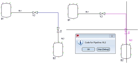
In older versions, connections between different pipelines could only be created via a separation symbol. This restriction can now be removed if desired. In the Connections tab of the Settings dialogue, activate the Allow connections between different pipelines.
Use the new Check part insertion to check whether a corresponding part in the 3-D layout plan has been assigned to a P+ID symbol.
The Show 3-D part function from the Edit menu has been moved to the Link to 3-D function group.
The check is performed if the Check symbol identification for uniqueness has been activated in the P+ID settings.
The check is performed if the Check symbol identification for uniqueness checkbox has been activated in the P+ID settings.
The identifications of two symbols are identical (and therefore not unique) if their entries match for the following dialogue types (the dialogue code is set in brackets):
For identification according to DIN:
For identification according to KKS:
If a non-unique identification is entered, the symbols that already have this identification will be listed in a dialogue box.
This new feature is only important if you use the HELiOS database for part data management.
The ignore industry pre-settings during part search option is set if you choose the default settings. It influences the part search process when assigning parts to symbols via the Edit symbol function.
This new faeture is only important if you use the HELiOS database for part data management.
If a pipe class has been assigned to a pipeline symbol, the corresponding Edit symbol dialogue will look as follows:
If you click Straight pipe, you can assign, in addition to the pipe class, a straight pipe from this pipe class to the symbol.
If a P+ID is managed via the HELiOS database, you can display the contents of document attributes of the corresponding document master (and the superordinate database project, if any) in the title block of the drawing frame.
As of HiCAD 2012, the attribute contents of part masters which are linked to the document master of the P+ID can be displayed in the drawing frame.
Related Topics
HiCAD P+ID • News 2010 (P+ID) • News 2011 (P+ID)
Version 1702 - HiCAD P+ID | Date: 9/2012 | © Copyright 2012, ISD Software und Systeme GmbH
 Example: