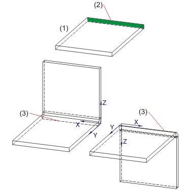
There are two functions for adding sheets with a bend zone:
![]()
Sheet Metal > Attach > Flange ![]()
You use this function to attach flanges across the entire length of a sheet part by identifying the connecting edge. The choice of connecting edge determines the direction of the new sheet.
The flange is added, taking into account the technology data. You can
use the right mouse button to call and change the technology data before
identifying the connecting edge. Select New > Base sheet  > Technology
datafunction to change the default setting of the technology data.
The technology data includes the sheet thickness. It must be the same for the entire bend part, both for the base sheet and for the flanges.

(1) Base sheet
(2) Connecting surface
(3) Connecting edge
![]()
Sheet Metal > Attach > Flange  > Attach flange, between 2 points
 ![]()
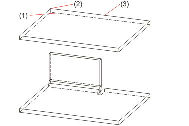
This fits the flange, bounded by means of 2 points, with a relief groove.
The flange is inserted without relief groove if you enter 0 for the values.
The height/length and the bend angle of the flange are defined in the Technology data dialogue window.

(1) Connecting edge
(2) First point
(3) Second point
![]() Please note:
Please note:
Related Topics
Version 1702 - HiCAD Sheet Metal | Date: 9/2012 | © Copyright 2012, ISD Software und Systeme GmbH