Isometry > Create > AutoGenerate isometry 
Plant Engineering > Isometry > AutoGenerate isometry 
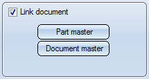
The drawing to which the isometric drawing belongs can now retain the pipeline, from which it was created, as a referenced part. In this case, you need to invoke the Link document option. Once generated, the item numbers of weld seams and parts are saved with the data of the original pipeline, and retained in the isometric drawing even if changed by re-creation of the isometric drawing.
Part master data and document master data for the pipeline are automatically created in the database. Attribute assignment can be preset, whereby you can specify diverse configurations and attribute assignments.

To specify attribute assignment, click the Document master or Part master button. To load a configuration, pick the appropriate name from the Configuration list box, and select OK to exit the window.
Please note the following:
In previous versions a Part geometry-Drawing link was created between the part geometry document of the pipeline and the layout plan, and a Part-Drawing link was created between the part master and the generated isometry documents. In particular constellations, this could lead to conflicts with Workflow functions. As of Version 2012, isometries in HiCAD will therefore use their own, isometry-specific links - by default, without release relevance and always linking to the part master.

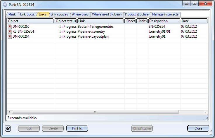
The pipeline part in the above example contains links to several documents: (1) "Part-Part geometry" link with the part geometry document (.KRA), (2) "Pipeline-Layoutplan" link to the layout plan and (3) "Pipeline-Isometry" link with a single, generated isometry document.
Old documents with the previous link variants can still be read, but please note that problems may occur with their editing (this applies in particular to isometry re-generation). It is therefore recommended to delete old isometry documents (if any) before isometry re-generation, e.g. by means of the "Reset isometry" option. If the new link types in HELiOS are not defined, an error message appears when you try to start the isometry:

The new link types should be created automatically when making an upgrade or a new installation of HiCAD/HELiOS. If the link creation fails, you need to create the links yourself, following the instructions given in the chapter Link Types for Isometries in Version 1700.
![]()
This option enables you to change an existing configuration. First select the required file from the Configuration list box. Right-click an entry in the Attribute list to call a context menu. The, Insert, Delete and Edit options are now available in the context menu.
To insert an attribute, proceed as follows:
To remove an attribute from a template, right-click the appropriate line and select the Delete option in the context menu.
![]()
Click the Create new button to create a new configuration. Specify a name for the configuration and then specify the required attributes.
HiCAD saves configurations to the WORKSHOPDAT.XML file in HiCAD’s SYS directory. Please save this file at regular intervals.
To remove a new configuration, click the Remove button.
 The configuration will be immediately deleted from the WORKSHOPDAT.XML file without any previous security prompts!
Related Topics
Generate Isometry Automatically (Iso) • Pipeline Isometry (PE) • Isometry Functions for the Layout Plan (Iso)
Version 1702 - HiCAD Plant Engineering | Date: 9/2012 | © Copyright 2012, ISD Software und Systeme GmbH