Move Points (PE)
Plant Engineering > Part Tools > Move points 
This function is very useful if you want to modify the layout of a pipeline. The following example is intended to demonstrate the function. Let us assume that a guideline was drawn and parts placed as shown below:
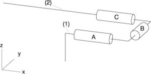
You now need additional space on the left of part A to insert a part between part A and the guideline corner, i.e. In other words you want to lengthen guidelines a and b, while simultaneously moving the U-shaped section of the guideline including parts A, B, and C in x-direction.
Proceed as follows:
- Set the appropriate projection, in this case Top view is suitable.
- Invoke the Move points function
- HiCAD asks whether the correct pipeline is active. You can now activate the required pipeline.
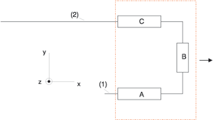
- Use the Specify rectangle option to drag a box - as shown in the illustration - completely over components A, B and C. Close box specification with END (right mouse button).
- You now need to specify whether the function should only move elements of the active part or all elements contained in the rectangle.
- For Displacement vector (..) Start point: select, e.g. the start point of the guideline (1), and for Displacement vector (..) End point: the end-point of the guideline (1), to specify the direction of the displacement vector.
- Enter the sum by which the length of a and b should be increased for the Total displacement. Please make sure that the direction of the vector is respected when specifying the sign. HiCAD now performs the displacement.
You can also enter 0 for Total displacement, and perform the moving dynamically with the mouse.
 Please note:
The function described above differs from the normal HiCAD 3-D function as follows:
- A pipeline part is activated before the moving.
- HiCAD displays (before the moving takes place) and moves guidelines covered by parts, as well as the otherwise hidden symbolic representation of parts.
- If a movement reduces the length of straight pipes and their associated guidelines to 0, they are automatically deleted.

Related Topics
Part Tools (PE) • Plant Engineering Functions
Version 1702 - HiCAD Plant Engineering | Date: 9/2012 | © Copyright 2012,
ISD Software und Systeme GmbH