Transform + Clone Part (3-D)
Transforming
a part means to assign it specifically to other parts of the drawing so
as to guarantee the technical function (e.g. shaft-cog wheel, valve flange-pipe
flange). In constructive tasks, this is generally done via the surfaces
of the parts and/or via marked lines or points, e.g. symmetry lines, midpoints,
centroids.
Transforming a part in 3-D space may require the following elementary
operations, in accordance with the 6 degrees of freedom:
- Move in x-, y- or
z-direction or
- Rotate about the
x-, y- or z-axis.
In addition, scaling of a part in x-, y- and/or z-direction may be required.
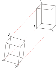
Three 3-D fitting point pairs are generally required for defining the
six degrees of freedom, e.g. when moving parts.
|

|
The figure shows the movement of a cuboid from the original position
resulting from the specification of the three fitting point pairs (1,1'),
(2,2') and (3,3'), i.e. the cuboid is rotated and moved. 1, 2 and 3
are the fitting points of the original position, while 1', 2' and 3' the
corresponding fitting points in the drawing, i.e. the new positions of points
1, 2 and 3.
|
You can copy parts that you require frequently
in the drawing. These copies which are the result of a transformation from
the original are called clones
in HiCAD.

Related
Topics
Transform
Part (3-D) • Clone Part (3-D)
Version 1702 - HiCAD 3-D | Date: 9/2012 | © Copyright 2012,
ISD Software und Systeme GmbH
