You can also use vector equations to define composite edges, the support
points being connected with lines oder circular arcs , depending on the respective function.
![]()
Sketch > Draw > Freehand > Vector equation 
The support points are connected by means of lines here. To construct the composite edge, for each of the x-, y- and z-components separately either a parametric equation with parameter T is specified or a composite edge the x-, y- or z-coordinate of which is adopted is identified.

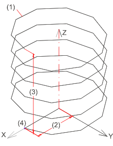
Approximated helixes with 5 windings, 50 segments and start angle 0 (between number of points and x-axis)
(1) Segment, (2) Average winding diameter, (3) Height, (4) Number of points
You need to specify each of the equations for the x-, y and z-component in turn, depending on T.
The following parameters are relevant for the helix:
|
r |
Average winding radius |
|
a1 |
Number of windings |
|
t1 |
Height of the helix |
|
i1 |
Number of points (= number of segments +1) |
|
w |
Start angle |
This gives rise to the central angle of the segment: a=a1*360/i1
For the helix T can be defined as an increment in the direction of the z-axis.
T=t1/i1, ![]() =a2*T with a2=a1*360/t1
=a2*T with a2=a1*360/t1
If a start angle w is taken into account, the following vector equations result:
X(T)=r*cos(w + ![]() ), Y(T)=r*sin(w +
), Y(T)=r*sin(w +
![]() ), Z(T)=T
), Z(T)=T
Next, the scope and the increment need to be specified for T, e.g..
Initial value=0, increment=t1/i1, end value=t1
You can also identify composite edges the x/y/z-positions of which are used instead of a formula for x/y/z. In so doing, you need to make sure of the same number of points and the orientation of the composite edges. Composite edges are treated like polylines in this case, i.e. only the start and end points are considered.
This method allows composite edges to be averaged and to be created from drafts. It is usually worthwhile to combine the parametric equations and the scope in a HiCAD macro, thus enabling the values for the input parameters to be varied.
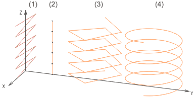
The figure shows helixes for different input values that have been created with the macro:

|
Variant |
1 | 2 | 3 | 4 |
|---|---|---|---|---|
|
Average winding radius |
50 |
50 |
50 |
50 |
|
Number of windings |
5 |
5 |
5 |
5 |
|
Height |
100 |
100 |
100 |
100 |
|
Number bof segments |
10 |
5 |
20 |
300 |
|
Start angle |
0 |
90 |
180 |
0 |
![]() Variant 2 has "degenerated" into a straight-line composite
edge consisting of 5 segments (points bound the segments), variant 1 into
a zigzag line and variant 4 shows a very well approximated helix of 300
segments.
Variant 2 has "degenerated" into a straight-line composite
edge consisting of 5 segments (points bound the segments), variant 1 into
a zigzag line and variant 4 shows a very well approximated helix of 300
segments.
![]()
Sketch > Draw > Freehand > Circular vector equation 
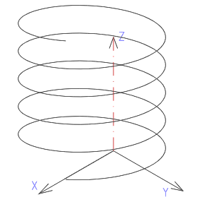
In contrast to the Vector equation function, 2 circular arcs that merge into one another tangentially are calculated at each of the support points here.

You can apply the specifications for the vector equation
in the same way to the circle vector equation - except for
parameter w. This gives rise to the following vector equations: X(T)=r*cos(![]() ), Y(T)=r*sin(
), Y(T)=r*sin(![]() ),
Z(T)=T Y(T)=r*sin(
),
Z(T)=T Y(T)=r*sin(![]() ),
Z(T)=T
),
Z(T)=T
Related Topics
Curves (3-D) • 3-D Sketch (3-D) • Sketch Functions (3-D)
Version 1702 - HiCAD 3-D | Date: 9/2012 | © Copyright 2012, ISD Software und Systeme GmbH