If the grid is activated, all points that you generate with the RETURN point option are referred to grid points. If a point grid is active, you can move the cursor as required, even between the grid points. When specifying the points in polyline mode, for example, you position the cursor on the individual grid points.
There are various ways of making the point grid visible on the screen. They can be selected by making corresponding entries in ALGPAR.DAT:
If you only want an outline of the point grid to be displayed, set the parameter to -1 in ALGPAR.DAT. Only one pixel per grid point is activated on the screen.
If the parameter in ALGPAR.DAT is set to 0, a circular signature is drawn for every grid point displayed. You can define the size of this signature in GRAPAR.DAT.
The grid can be displayed on the graphics screen in the form of grid lines that are orthogonal to one another. For this, the corresponding parameter in ALGPAR.DAT must have a value between 1 and 9. This value is used at the same time as a line type for the grid lines. This display type is used if you want the grid to act as a construction aid.
![]() You need to re-start HiCAD for the changes in ALGPAR.DAT
to take effect.
You need to re-start HiCAD for the changes in ALGPAR.DAT
to take effect.
![]()
![]()
2-D Geometry > Construction Aids > Grid  > Point grid ON
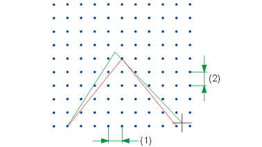
You use this function to define and activate a point grid. All points the coordinates of which are obtained by converting the cursor position are rounded to the nearest grid point if the grid is activated. Specify the distance in x- and y-direction for the point grid. The default setting in HiCAD is 10 mm.
![]()
![]()
2-D Geometry > Construction Aids > Grid > Point grid OFF 
You use this function to deactivate a point grid you have defined. All points are displayed, according to the point options used.
![]()
Related Topics
Auxiliary Lines (2-D) • Grid (2-D)• Angle Grid (2-D)
Version 1702 - HiCAD 2-D | Date: 9/2012 | © Copyright 2012, ISD Software und Systeme GmbH