3-D FFS > From c-edges > Connect cross-sections 
![]()
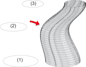
The displayed model was created by placing 1 cross-section on 2 guidelines. These cross-sections were connected with each other by means of interpolation.
|
|
|
|
Original model |
|
|
|
|
|
Interpolation without connection constraints |
Interpolation with connection constraints Start/End: perpendicular |
|
|
|
|
Shaded representation |
|
![]()
Here, 3 circular cross-sections were connected with each other. The following connection constraints were defined:
 (automatic)

(1) Start cross-section, (2) Intermediate cross-section, (3) End cross-section
![]()
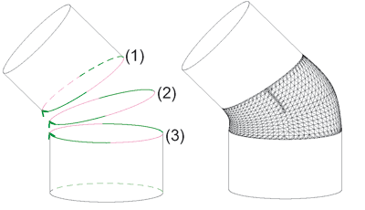
Even boundary curves of solids can be connected with each other, by including of intermediate cross-sections. Here, however, it is important that all cross-sections have the same number of edges. Furthermore, boundary curves of solids need to be defined as hyperedges (if required, after previous division). In the image shown below the boundary curve (1), the intermediate cross-section (2) and the boundary curve (3) were connected with each other. The two boundary curves were previously divided and hyperedges were derived subsequently.
The following connection constraints were defined:
 (automatic)

Solids with intermediate cross-section and connection constraints
Related Topics
Interpolate Cross-Sections (3-D FFS) • Overview of Functions (3-D FFS) • Freeform Surfaces
Version 1702 - HiCAD Freeform Surfaces | Date: 9/2012 | © Copyright 2012, ISD Software und Systeme GmbH